Last update 24/2/2002
Details on rotor arm spigot fitting
Details on fitting distributor cap to converted VVC head
Details of VVC conversion kit
Details of cam fouling and fettling of follower bore tops
ACKNOWLEDGEMENTS
You are visitor number since 19
September 1999
Last update 24/2/2002
Details on rotor arm spigot fitting
Details on fitting distributor cap to converted VVC head
Details of VVC conversion kit
Details of cam fouling and fettling of follower bore tops
ACKNOWLEDGEMENTS
The information contained below is the result
of work done on the Rover 'K' series engine by myself (Dave
Andrews) and Bernard Scouse - a friendly and
patient Elise owner who has used his car as a guinea pig for engine developments. Bernard
has a web site here where
you can find details of the excellent airboxes he makes for the Caterham and Elise. Others
who have provided various engine parts for modification are Caterham and Elise owners Tor Atle, Paul
Ranson , Johnty Lyons, Steve Butts, Mike
Bees, Mike Dresser, Peter Carmichael, Simon Parker , Rob Day, Ian Coburn, Edgar Shih,
Andreas Rektenwald,Luca Adami, Stefan Winquist, Rolf Plus, Stein Oexseth, Simon Thornley,
Warren Johnson, Mike Williams and many many others all of whom have heads modified to
various specifications and solid cams fitted with followers and dowels modified by myself.
Bernard has spent many hours designing and making the inlet manifolds and
airbox/backplates / airboxes used with the Jenvey throttle bodies. He has also done
without his favoured Elise for weeks at a time while it was being used as a test platform
for the Emerald ECU. We hope that the information following may dispel a few of the myths
surrounding the tuning of the 'K' series engine and answer a few of the questions usually
posed by owners of K equipped cars. If nothing else it may help to show the choices
available and how things can be done without unnecessary or excessive expenditure. Neither
Bernard nor myself have any connection whatsoever with any tuning company nor supplier
other than as customers.
There are many Caterham and Elise owners who have been inspired by the details on
this page and undertaken the modifications themselves in the true spirit of DIY,
many of these have come to my garage for advice or for some sample port work with them
undertaking the finishing work. Some of these are Martin Lewis (Elise), Mick Smith
(Caterham), Rob Walker (Caterham), Brian Bannister(Caterham), John Howe (Caterham), Lorne
Mason, Alan Betts, Dale Cordingley, Simon Kelly , Ray Pearce , Mark Boardman, Julian West,
Rob Turnock and many others whose names I can't remember. All have acheived worthwhile
results and the satisfaction that comes from having done the job themselves.
The following two link have been added since the articles are often requested
Fitting verniers and timing cams
Fitting Jenvey DTH throttle bodies
Navigation around the page may be easier using the following links.
Engine general
Bolt-on upgrades
Selecting a head to modify
Cylinder head discussion
Big valve conversions
Paul Ivey valves
VVC Cylinder head
VHPD Cylinder head
Pictures of standard and modified heads
Flowbench comparisons
Graphs of flowbench comparisons
Valve spring caps
Valve stem oil seals
Camshaft and cam drivetrain
All about cam followers
Solid followers
Converting hydraulic followers to solid
Drawing of solid follower conversion shim
Adjustable followers
Follower weights
Re-using existing followers
Cam timing, verniers vs. offset dowels
Drawing of offset dowel for cam timing
Fitting vernier pulleys
Timing the cams using 'lift at TDC' method
Valve/piston clearances
Camshaft choices
Piper Cams listing for K engine
Induction and engine management systems
EMS choices
Emerald M3D information page
Induction system choices
Individual throttle bodies
Dual throttle bodies and manifold
Direct to head bodies
Airbox kit for DTH bodies
Jenvey induction page
VHPD Induction system
R500 Induction system
Exhaust manifolds and system
Bottom end strength
Pictures of damaged std. piston and forged replacement
Lubrication, oil coolers, dry sump etc.
Selection of tooling for head modification
Modifying the K series cylinder head
Waterway modifications to K head
Sleeving of waterway drillings
Modifying the VVC/VHPD cylinder head
Replacing valve guides
Fitting the rotor arm spigot to the inlet cam
Retaining the distributor cap with VVC head
Torque wrench settings
Rolling road results
Elise / VHPD rolling road results
Mike Bees 1700K rolling road results
Rover ‘K’ series engine
The ‘K’ series engine as used in the Caterham seven and Lotus Elise, is a compact and light unit capable of high specific outputs. It comes in three displacements, 1400cc, a larger bored 1600cc and a stroked 1800cc. It is a popular engine in motorsport due to its relatively light weight and performance potential. The cylinder head is of twin overhead cam design, 4 valve with a classic pent-roof combustion chamber design. Because of its inherent under-square nature its ultimate tuning potential is inferior to a Cosworth BDA , YB or Vauxhall 16v since the available valve area is not as high, but it is streets ahead of designs such as the venerable crossflow and pinto. As installed in standard form it is well below its optimum. It is unusual in its construction in that the engine is of 'sandwich' design, the head is not bolted to the block , instead long bolts are used which sandwich the block assembly together between an engine bottom plate and the cylinder head.
Things which make the ‘K’ series difficult to tune are
A non programmable ECU (the Rover MEMS) |
|
Restrictive plenum based injection system which has to meet emission / economy requirements |
|
Conservative valve and port sizes in the cylinder head |
|
Conservative cam timing and lift, coupled with hydraulic followers |
|
Bottom end strength |
The after market tuning industry is awash with claims of extra horsepower for the K series, some of these are ludicrous, some are genuine. All told it is confusing for the newcomer or the inexperienced owner who does not necessarily know what is available or what works and what doesn’t, it is very easy to be sold a ‘pup’.
Bolt-on engine upgrades
There are bolt-on kits that have started to
appear and these give a worthwhile performance boost. There is the Caterham Supersport kit
which is a revised MEMS ECU and cam upgrade and includes an airfilter and plugs, the cams
retain the standard hydraulic followers which in turn limits both duration and lift, the
current price of this is £865 + VAT, it upgrades the engines output to around 138BHP.
This is available from Demon Tweeks. Southern Carburettors do an
induction kit based on Jenveys single throttle bodies on a custom made manifold, together
with a pre-progammed GEMS ECU, this retains the standard fuel rail/regulator, injectors
and sensors from the std injection system, The ECU is a straight replacement for the
existing MEMS. The current price of this upgrade is £1575 + VAT, Southern Carburettors
can be contacted at 0181 540 2723 or via their website. There are other
‘bolt-ons’ from QED which comprise cam and throttle body kits together with a
replacement DTA ECU.
One particularly effective upgrade is a cam change, both the 1.6 and 1.8 K engines
benefit from fitment of better cams, the Piper BP270 cams or the older 623 grind can be
used very effectively but I would recommend the fitment of verniers to accurately time the
exhasut cam and retain a perfect idle, these can boost the peak power by 10BHP or more
with a corresponding increase in torque, the engine also feels much more willing to rev.
Coupled with other bolt on mods such as an improved airfilter and exhaust some satisfying
gains can be made.
Emerald Electronics (0207 737 7114 EmeraldM3D@aol.com
)have pioneered a purely bolt on upgrade consisting of a pair of cams, a pair of direct to
head throttle bodies with airbox and their M3DK plug compatible ECU with a suitable map,
this has been shown to give a verifiable 166BHP on an otherwise standard 1600K series
engine with decent exhaust manifold. The overall cost of this conversion is around the
£1800-2000 mark.
All of these bolt on kits give good results but will be limited by the breathing ability of the standard head and the need to retain hydraulic followers. The VVC head has larger valves and better porting but it’s scarce and expensive and needs much modification to use normal cams. Minister are experienced in reworking K series heads and SP Performance continue to make almost surreal claims about their handiwork. At present it is not an easy task to decide what to do to give the engine more go or who to buy the kit from.
At a recent Lotus Elise rolling road 'shoot-out' at Dave Walkers workshop various bolt-on upgrades were tested and evaluated together with some more involved conversions. The results of this will be published shortly in CCC magazine, it should make interesting reading. To see the results as published to the Lotus list on the web click here.
The first decision to make is whether you are prepared to get your hands dirty and remove the cylinder head. If not then bolt on kits are as far as you can go and it is unlikely that you will be able to fit the more radical cams with solid lifters. Solid lifters can be shimmed with the engine in situ but it is not an easy task and its likely that the standard springs will go coilbound with the increased lift. It is questionable whether it is worthwhile using cams with more than 275 degrees duration with the standard cylinder head, especially on the larger capacity engines. Power gains of up to 40BHP or maybe more can be had by using these bolt on kits, but considering their price some of them don’t represent good value for money. If you are after more serious horsepower then the cylinder head definitely needs to be removed for attention.
Selecting a
cylinder head for modification
If you are considering modifications to your engine which include changes to the cylinder head it is often very convenient to source a spare head and modify this in advance. When the porting is complete the original head can be sold on to someone else who may want to do the same. Make sure when you buy a secondhand K16 head that you know what you are buying. Be sure to select the right sort of casting, early 1.4 heads (known as low-port) are unsuitable for serious power outputs especially on 1.6 and 1.8 engines.
Low-port heads can be identified by two characteristics, the first is the size of the inlet port entry which is around 31mm or so, later heads (high-port) have 34mm port entries. The second way to identify a low-port head is to look at the top of the inlet flange where the head casting number is, this is just above inlet port number two. Behind the flange the casting drops down to the top of the inlet runner, on the early low-port castings this drop is around 6-8mm, on the later high-port 1.6/1.8K heads, the drop is only 1-2mm with the inlet port being visibly higher.
On a high-port head if you look inside the head casting from the top down through the follower bores you will see that the casting is visibly raised between the spring seats towards the outside of the head to accommodate the higher port line. It is not possible when modifying older low-port heads to raise the port line high enough without holing the casting, nor can the port size be made large enough when installing larger valves.
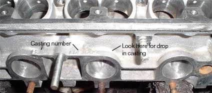
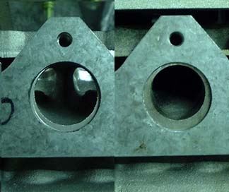
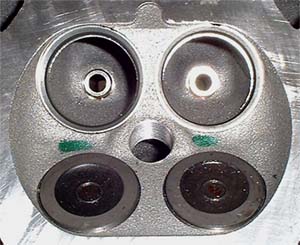
Below is a picture showing the inlet ports from a high-port and low-port head alongside
one another, the heads are upside down but the difference in port size and orientation can
be clearly seen, don’t spend good money or a lot of time on an early 1.4 casting..
Below is a list of casting numbers from the various heads produced for the K series, the
casting number can be found on the top of the inlet flange over inlet port number two.
Casting number Port size Head type
LDF 10091 31mm 1.4 K low port
LDF 10233 34mm 1.6/1.8K high port
LDF 10239 34mm 1.6/1.8K high port
LDF 106350 34mm 1.6/1.8K high port
LDF 105460 36mm VVC
LDF 106970 36mm VVC
LDF 10290 36mm VHPD
The list is not exhaustive but gives an idea of the series of numbers for each type of casting. The chances are that if your casting number is near or less than the one for the 1.4 low-port that the casting is unsuitable.
Make sure you inspect the head thoroughly to spot any damage or missing components as these can be ferociously expensive if bought from Rover. In particular make sure the head casting is not cracked and that the followers (if you are retaining them) are not rusted or heavily pitted. If in doubt reject the head. Look carefully for a casting shift, this is where the casting centre and machining centre differ, this can cause the valve seat inserts to be offset in the ports which can compromise porting. Look for excessive recession of the valve seat inserts in the combustion chambers, this is easy to spot and creates a large lip between the seat insert and the chamber. Buying a bare casting is not always a good economic proposition unless you get it at a good price and you are buying new valves anyway.
Standard K16 Cylinder Head
When the cylinder head is examined it becomes clear that the engine was designed as a smaller capacity unit, the valve sizes and port sizes are inadequate for the larger capacity engines.
Good results can be achieved by simply porting the standard head, retaining the std. valve sizes (27.5mm inlet 24mm exhaust). If careful attention is paid to the port size, valve throat shape and size and to the valve guide bosses together with careful reshaping of the back/seat of the valves and the seat inserts, the resulting increase in volumetric efficiency is quite marked. If done in conjunction with a cam upgrade and suitable remapping of the fuelling worthwhile gains can be made. Even if the standard cams are retained, torque can be increased significantly.
For serious horsepower, a big valve conversion to the head or head replacement is required and this can be done at five levels:-
1 |
Bigger valves retaining the standard inserts (29.5mm inlet, 26mm exh) |
2 |
VVC sized inlet valves running in new larger inserts (31.5mm inlet, 26mm exh) |
3 |
VVC head with solid cam conversion (31.5mm inlet, 27mm exh) |
4 |
VHPD head (31.5mm inlet 27mm exh) |
5 |
VVC/VHPD head running larger 32.5mm inlet valves |
A big valve head used in conjunction with a cam upgrade and suitable changes to the induction can transform the nature of the engine from a relatively sedate unit into a free-revving barnstormer.
Big valve conversions
Paul Ivey (Race Engine Components of West Bromwich) manufactures superbly designed valves, he can supply oversized inlet and exhaust valves which will just fit the standard inserts in the K16 head. These are single piece valves manufactured from 214N stainless steel forgings with tuftrided stems, the inlets are 29.5mm , the exhausts are 26mm. The valves are of waisted stem design with very low profile heads. This improves the flow over the back of the valve considerably; these valves fitted to a properly reworked cylinder head will flow 30% more air than a standard head and more air than a standard VVC head, flow bench comparisons are available by clicking here. These are available ex-stock and despite being stronger lighter and better designed only cost around 50% of the price of the OEM valves from Rover.
There are some pictures of a standard K16 head, a first stage big valve head and a standard VVC head and a modified VVC head on the K Head Page.
VVC sized inlet valves can be fitted to the
standard head provided that the inlet seat inserts are replaced with larger ones. Paul
Ivey also manufactures VVC sized inlet valves to the same design as the 29.5mm ones, again
they are a single piece valve of superior design. VVC valves are 31.5mm in diameter and
require an insert size of 32mm or so external diameter putting into the head. VVC valves
are sometimes difficult to obtain from Rover, without question the VVC sized valves from
Paul Ivey are vastly superior and less expensive, however the ones from the KV6 are
virtually identical to the VVC ones if you must buy from the OEM. The ports need some
extra enlargement to meet the airflow requirements but this can be achieved with care. No
doubt larger valves can be fitted and I have heard of the K8 (8 valve K series) valves
being fitted to the head (these are 34mm) but it is questionable whether the ports could
meet the airflow required without risking porosity in the casting, they are also larger on
the stem diameter which creates a problem with guides sizes and with collets and caps.
Paul Ivey can manufacture to order valves with 32.5mm and 33.7mm heads for use in K16 and
VVC/VHPD heads. There may well be a bore/piston clearance problem on the smaller capacity
engines when using these larger valves.
A VVC can take a 32.5mm valve in the standard insert and the increase in ariflow when
the head is properly modified is worth having, a fully modified VVC head fitted with
32.5mm inlet valves can flow 136CFM which is a 35% increase over standard.
To see flowbench comparisons between the standard K16 head, the VVC/VHPD casting and some modified K16 and VVC big valve heads done by myself click here.
For an engine to need the larger 34mm valves, significant RPM would need to be reached especially on the smaller engines. If engine speeds of greater than 7500RPM are to be used on a regular basis careful attention would need to be paid to the bottom end, primarily pistons (on earlier engines) and steel crank/rods. There has been talk of instability in liners at these higher RPMs specifically over 8500 so this should be taken into account. Rumour has it that the supercharged ‘K’ engine suffered from liner movement/failure due to the extra stresses involved.
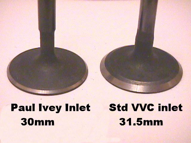
Below is a photograph of the Paul Ivey valves in comparison to the OEM originals, these clearly show the superior design. Note the 'wasted' stem and flatter profile head together with the thin seat radiused into the back of the valve, this all helps to improve flow dramatically at lower lift.
Futher below are some words and schematics showing how and where the head needs to be modified for the various specifications, standard valves, 30/26mm valves and VVC valves. If you are not confident in undertaking this work yourself then there are companies who will be happy to relieve you of your cash. QED, Minister, Jondel Race Engines and SP Performance are all known for their skills in head modification and prices range from a reasonable £250 to an unreasonable £800.
For those with the confidence and skill to undertake the head modifications it can be a very satisfying undertaking since the cost are very low, £25 worth of high speed steel rotary cutters is enough to get you started. Since the material being fettled is aluminium alloy, it is a fairly straightforward task, especially when compared with modifying a cast iron head.
In addition to the cutters you will need some
abrasive mops which can be obtained from the ‘Frosts’ catalogue, they do an
inexpensive porting kit containing all that is needed to obtain a good finish on the
ports, throats and combustion chambers. Click here to go to the Frosts website.
| Paul Ivey valves | ||||
| Size in mm | Description | Part no. | Price |
|
29.5 |
K16 big inlet | REC739 |
10.29 |
|
26 |
K16 big exhaust | REC740 |
10.29 |
|
31.5 |
VVC/VHPD Inlet | REC757 |
12.36 |
|
27.3 |
VVC/VHPD Exhaust | REC758 |
12.36 |
|
32.5 |
VVC big inlet | REC767 |
13.28 |
|
33.5 |
VVC big inlet (K8 size) | REC768 |
15.68 |
|
28.3 |
VVC big exhaust | REC783 |
13.6 |
|
VVC heads
The VVC head is a superior casting which as
well as containing the VVC mechanisms also has larger valves (31.5mm inlet, 27mm exhaust)
and revised port geometry. The inlet ports are larger by a mm or two and the port angle is
higher by 1.5mm giving a straighter shot into the cylinder. The cam followers are also an
improved design and are a little lighter than the normal K16 ones, they also hold less oil
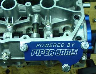
when charged. The VVC head can be fitted to a non VVC engine utilising solid cams rather
than the VVC ones, a conversion kit is available from Piper which contains all the bits
necessary. It is however a a little expensive exercise since VVC heads are relatively
rare, second-hand price is around £350 and a blanking plate conversion kit from Piper
costs around £95. You cannot fit a normal inlet cam to the VVC head since the end bearing
sizes are larger, nor can a replacement cam be made from a standard cam blank, cams for
the inlet side of a VVC head need to be machined from a special blank which makes them a
little more expensive.
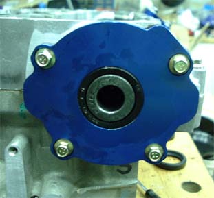
Piper conversion kit for VVC head to take solid cams
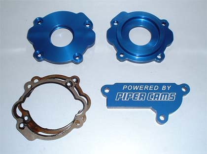
Kit as fitted to VVC head
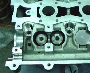
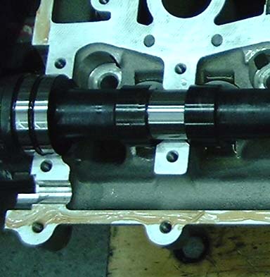
VVC head showing larger bearing and with VVC inlet cam fitted
To get the best from a VVC head it does require some porting both to the inlet and
exhaust ports. Obviously there is less work to do since the inlet port is already more
generously proportioned. A stock VVC head is a worthwhile upgrade to 1.6 and
1.8 engines.
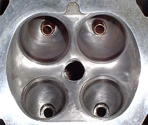
The very least you should do when fitting a VVC head is to remove the recession
ledges around the inlet and exhaust seat inserts in the combustion chamber and smooth/ease
the ledges and ridges around the inserts in the valve throats as shown in the photos
below..
The VVC head will take larger valves in the standard inserts, Paul Ivey manufactures
32.5mm valves which will just fit the standard inserts, these make a good upgrade when
airflow requirements are very high.
Unless you come by a VVC head at a very good price it is probably more economical to use the base casting and have it inserted for VVC sized inlets. To have this done together with new inlet and exhaust valves from Paul Ivey is still less expensive than sourcing a VVC head and the valves are definitely superior in design. However a standard head that has been inserted will need major reworking to the valve throats and ports in order for the larger valves to be effective and it will ultimately flow less air. The practical limit for a K16 type head with 29.5mm/26mm valves is around 200-210BHP, VVC or larger sized valves with new inserts may give 220BHP+.
The VVC heads I have recently prepared for Mike Bees and Peter Carmichael used 32.5mm inlet
valves and flowed 36% more air than a standard VVC head, the potential of the VVC head far
outstrips the standard head even when it's fitted with 33.7mm inlet valves. Comparative
flowbench results between Mikes head and a full race professionally prepared head with
these 33.7mm valves are available by clicking here. When Mikes
Caterham 1700cc K series was run up Emeralds rolling road it made over 240BHP, Peters
1800K special K made 250BHP.
There are pictures of a standard and modified VVC heads on the Khead
page.
VHPD Heads
These heads are essentially a hybrid between the normal K16 head and the VVC head in that they use the same base casting as the K16, but with the VVC ports and chambers cast in without provision for the VVC gubbins. The VHPD head uses the same sized valves as the VVC head. If complete the VHPD head comes with Piper 872 cams and solid followers together with special valve spring caps with a raised ring to contain the follower shims.These are even more rare than the VVC heads since they are made to special order, but if you do find one then it is the ideal head to use as a basis for your performance engine since there is no VVC paraphernalia to blank off and it will take a normal type inlet cam. The downside is price, I have heard of bare castings changing hands at £1200, this is a ludicrous price since the cost of buying and converting a VVC head is much less and they are essentially the same flow wise and you still need to buy valves, cams, followers, springs, verniers/sprockets, caps and collets. The VHPD head is an off the shelf casting and has no additional hand finishing applied. Identical results can be expected from a well modifed VHPD head as from a modified VVC one. I have recently modifed a VHPD head to take larger 32.5mm inlet valves, the specification and results were pretty much indentical to the VVC head.
Flowbench Comparisons
To see flowbench comparisons between a standard K16 head, a standard VVC/VHPD head and some modified K16 heads click here. I have now fully reworked a standard VVC head using Paul Ivey replacement 32.5mm valves and the flowbench results have been very pleasing in that the peak flow is 20% better than a reworked K16 head. Obviously the VVC/VHPD has more ultimate flow potential since there is more material around the ports and they can be enlarged to a greater degree.
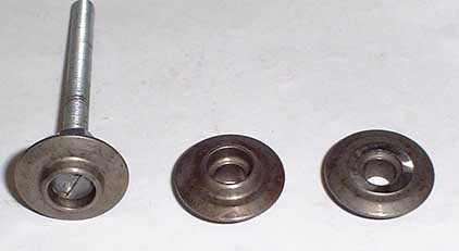
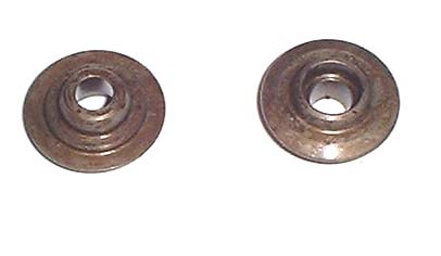
There are two types of production spring caps currently used on the K series, the standard sintered caps and the VHPD style caps. The VHPD caps are similar to the standard caps except they are made from better material and have a support ring for the shims used with the solid followers utilised in the VHPD engine. Neither type has a proper support platform for a second valve spring. The standard caps are not really suitable for RPM above 7800 or for very high spring poundage and although the VHPD ones are somewhat stronger they cannot be used unmodified with the standard followers, they can only be used with proper (read expensive) solid followers.
Standard caps
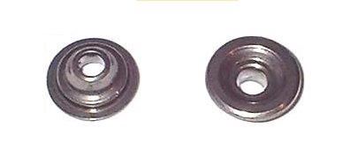
VHPD caps
If you are fitting double valve springs to your head you will need to fit steel
caps in order that the inner spring has a proper defined platform to sit on since the
standard and VHPD caps are not strong enough to be machined for a secondary spring
platform. Alternatively if you are contemplating RPM over 8000 then steel caps would be a
wise investment. The steel caps can be used with single or double springs.
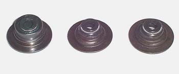
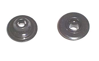
Piper steel caps
Piper do a suitable steel spring cap both with (SC3) and without(SC19) a support ring
for the solid follower shim. Those of you who will be using converted hydraulic followers
need to note that the nose of the follower will foul on the shim support ring of this type
of cap and the VHPD cap so it is necessary to modify the cap to remove the ring. If you
are ordering steel spring caps from Piper and you are using converted hydraulic followers
ask for the caps with no support ring, it will make your life easier.
If you need to remove the support ring from a steel or VHPD cap it is easily done by
mounting the cap on a countersunk headed setscrew. The cap can then be offered up to a
bench grinder to remove the offending ring. If you do not remove this ring then there is a
very real danger of the follower hammering the cap which can cause a valve to drop with
disastrous consequences.
Piper steel caps before and after modification, showing how to mount the cap
The early type of valve stem oil seal (left) is not suitable for double springs since it has too large a diameter, the later thinner type comes in two variants, one variant has no defined spring platform for an inner spring(middle) , the other has a flat platform for the inner spring to rest on (right). If you are using single springs then any of these types is suitable, if you are using double springs then make sure that you have the type with a flat platform for the inner spring.
Camshaft, followers and drivetrain
On examination, the cam follower and cam lobe dimensions are generous and the cams are well located. The lobes are slightly narrow but this does not in itself prove a problem. This gives potential for more radical and aggressive profiles provided that mechanical rather than hydraulic followers are used.
Hydraulic followers can suffer from three main maladies:-
Pumping up, where the follower solidifies too early during the lift ramp of the cam and over-lifts the valve, this can happen when an engine is over-revved.
Pumping-out where oil is evacuated from the follower causing the follower to solidify too late in the lifting ramp and the valve is under-lifted, mainly caused by too fast a lift or too wide a duration.
Oil aeration which allows the hydraulic lifter to be compressed rather than solidifying on lift, this is the main cause of the K series ‘rattle’.
Of these i) is the most dangerous since it can lead to valve/piston contact, ii) and iii) just cause the engine to rattle and subject the follower and cam to shock loads which should have been absorbed by the take up ramp designed into the cam profile. Since ii) and iii) also reduce the lift and effective duration of the cam, the engines performance is seriously affected as well. All in all hydraulic followers and aggressive cam profiles are not a happy combination.
If the duration of the cams you are intending to use is 274 degrees or less and the lift is less than 10mm then the standard hydraulic followers can be used relatively safely. All that is required is a light planish on the existing followers and liberal coating with cam lube for them to be suitable for re-use.
There are three types of hydraulic follower fitted to the K16 engine, early followers which are rather heavy and have small oil hole drillings, later followers which are somewhat lighter, have smaller oil reservoirs and a large chamfer leading to the oil drilling and VVC followers which have a more compact central mechanism and much smaller oil reservoirs. The favoured type are the VVC followers which are lighter and contain less oil when full.
All 3 types of followers can be converted to solid operation and there is functionally no difference between the early and late types, the modification made on the late type of follower were to improve oil flow into the follower, when converted to solid , oil flow into the follower is not necessary.
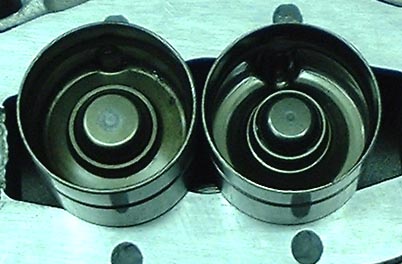
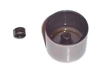
The Picture below shows a standard K16 follower on the left alongside a VVC follower
Mechanical or solid followers are available from Arrow Precision, Piper, Kent Cams, Warrior and Dave Newman. These are are not cheap (£200-400 including shims) and must be shimmed properly in order to operate satisfactorily, this is a time consuming and expensive operation. Any cam with more than 274 degrees duration or 10mm lift should use ‘solid’ followers.
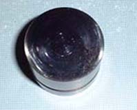
The followers fitted to the VHPD, R500 and some Caterham racers are of this solid type and have a different construction to the hydraulic type being a hollow bucket with a central pillar which operates on the shim. The shim sits within a locating ring on the spring cap, in a similar manner to the converted hydraulic followers, the shims are used to set the appropriate valve clearance between cam and follower
Below is a picture of a Piper solid follower and shim, the shim in this case is one produced by me, there are other types available which are simple biscuit types
Converting followers to solid operation
Looking at the standard hydraulic followers, it is relatively simple to convert these to ‘solid’ by using a custom made shim, these will need setting up in the same way as normal solid lifters. Similar shims are available from Cosworth at £5.50 per follower or John Wilcox at £3.50 per follower. I am currently looking into small scale production of these shims in tool steel, through hardened for around £2.00 per follower, these are satisfactory for all but the most stratospheric RPM. If you have a tame machine shop locally then the shims to convert the std followers are easy to make. The dimensions for manufacture are shown in the attached drawing, the standard followers are straightforward to convert. Converting your existing followers will save a lot of money when changing cams and is a tried, proven and acceptable way of doing things. If you can find VVC hydraulic followers they are somewhat lighter than the standard ones and have a much smaller diameter central hydraulic mechanism and oil reservoir, converting them to solid can be done in the same manner as with normal followers but the shims are a little smaller, I have a batch of the VVC shims manufactured and available.
Click here for diagrams of the solid tappet conversion
Below are two converted followers, the shims which convert the followers to soild operation are on the right, the central pillars of the two followers with the hydraulic valves removed are on the top left and middle, the main bodies of the followers are shown at the bottom with the oil holes soldered and the locating shield drilled in four places to ensure that the follower does not fill with oil. This makes a reasonably light and very inexpensive solid follower.
![]()
There is a weight saving to be made by using genuine solid
followers over converted hydraulic ones which may be worth having if the engine is turning
very high RPM, however converted hydraulic followers function perfectly well and have been
used in engines which regularly turn 8500RPM. Genuine solid followers are quite expensive
and the saving made by retaining your existing followers can be used to finance other
areas of engine development.
Dave Newman cams now produce an adjustable solid follower which has no shim, essentially it is the same as the Piper follower in construction but with the addition of an adjustable hardened grubscrew and locknut in place of the shim which can be screwed in and out to set the valve clearance.
Early K follower 56gms
Later K follower 53gms
VVC follower 48gms
Piper solid
44gms
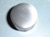
Although strictly speaking followers should be replaced when fitting new cams, this is largely unnecessary provided the followers are in good condition. Whether or not you are converting the followers to solid operation they should be planished before fitting with new cams so that the surface is perfectly flat and the new cam beds in correctly. The followers can be planished by placing some P240 wet/dry paper upturned on a truly flat surface (a metal bench or small sheet of glass). The flat surface of follower is then rubbed over the surface of the abrasive paper with a slow circular motion, lubricate the abrasive paper with WD40. Discard any followers which have heavy pitting or heavy rusting, these will not be suitable for re-use. Light scuffing and other light radial marks can be removed by planishing. Inspect the surface of the follower regularly, and turn the follower constantly. The planishing is complete when the face of the follower has a burnished appearance and none of the original wear marks or scuffing is visible from any angle.
Below are pictures of a follower before and after planishing, note the radial marks and light scuffing on the follower surface before planishing, this is normal.
Cam timing and verniers/dowels
When fitting after market cams you will no doubt be badgered into purchasing vernier pulleys to help time them in, these are expensive items. Verniers are very effective and certainly look smart on an engine, however if you are serious about competition I would recommend running a cover over the belt and pulleys. A simpler and more cost effective solution than verniers is to use offset dowels to correct/set the cam timing, these can be made very cheaply (£4.00 or so each) and once fitted perform an identical function. They do not have the visual appeal of a set of verniers but they free cash that can be spent on more productive areas. Offset dowels and keyways have been in use for many years and are an acceptable way of varying valve timing. I use offset keyways on my aspirated Cosworth and they are functionally perfect. These have proved difficult to have made so I make them here , I have limited supplies at £18 per dowel, if that seems expensive then feel free to have them made elsewhere, all the information you need is available via the link below. There is a balance to be had between the time taken to dial in the timing with offset dowels and the cost of verniers which make the job a lot more straighforward, you also need several different offset dowels in roder to correctly set your timing, if time is not an issue then they are effective, if however you are paying for the time tken it might be cheaper and easier to fit verniers. An alternative is to make dowels with a 15 degree offset and by carefuk rotation of the dowel in the cam hole you can acheive any offset you like from -15 to +15 degrees from the pulleys normal position.
Click here for diagram of offset dowels for K Series cam timing
The only disadvantages with offset dowels are that the offset required
isn't known until you come to do the cam timing itself so it is neccesary to have several
dowels available with different offsets in order to time the cams correctly and also that
you need to remove the cam sprocket to swap the dowel. If you do decide to fit verniers
they undoubtedly make the job of setting the cam timing much easier, but if you are
prepared for the extra work involed with offset dowels then there is a saving to be made.
An alternative and even cheaper way of allowing the cam timing to be varied is to elongate
the dowel slot in the cam sprocket.
Fitting vernier
pulleys
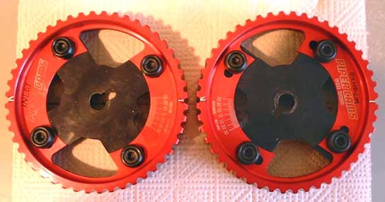
The standard cam sprockets on the K series come with alignment markings and specific
dowel positions for the inlet and exhaust cams which allow error free assembly and initial
cam timing. Vernier timing wheels such as those supplied by Piper are not 'handed' in this
respect, both verniers are identical and they do not have alignment markings. This can
make the initial timing of the cams when first fitting verniers a bit of a problem.
Before removing the old sprockets it is wise to turn the engine to 90 BTDC until the
timing marks line up as per the picture below.
A foolproof way of ensuring that the cams are initially correctly timed with the
verniers is to transfer the timing marks from the old cam sprockets to the verniers in the
correct position. The first step is to designate one of the vernier pulleys as an inlet
and the other as an exhaust and then mark the pulleys accordingly.
Following this the horizontal marks on each original pulley can be transferred by
laying the original pulley over the new vernier and aligning the appropriate dowel slot on
the old pulley with the dowel slot on the new one, the picture below shows the alignment
markings transferred onto the verniers from the original sprockets with the verniers
aligned how they should be for fitment to the engine when the engine is at 90 degrees BTDC
(before top dead centre). Note the arrows on the original sprockets which are marked as
'exhaust' are represented by a second scribed line on the verniers forming a simple
arrowhead.
Before fitting it is wise to advance the exhaust vernier by 10 degrees and retard the
inlet vernier by 10 degrees, this lowers the lift at TDC and therefore makes the cam
timing very safe prior to fitment and final setting.
Setting the cam timing using 'lift at TDC' method
By far the best way of establishing the correct cam timing is to measure and set the valve
lift at Top Dead Centre on the non firing stroke. The lift at TDC for each of the cams in
the Piper range is given on the Piper page, note that this may be
different for the inlet and exhaust cams of a pair. Once your verniers are fitted it is
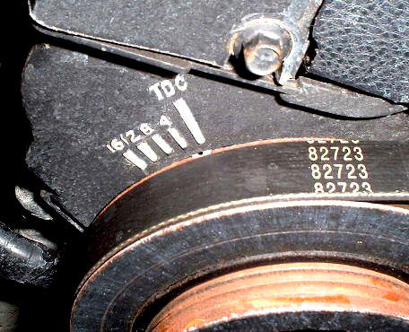
necessary to establish TDC for cylinders 1 and 4 on the engine, this is actually marked
with a small embossed pattern on the front timing cover and a corresponding small notch on
the back face of the pulley, it is probably a good idea
to mark the embossed line for TDC (this will be the last line on the right in a group of 4
lines on the cambelt cover) and the notch on the back of
the pulley with a small dab of white paint or similar to make it easy to spot. The picture
below shows the timing marks with the crank aligned at TDC
To establish the correct cam timing you will need a dial gauge with a suitable stand or
mounting strip , an allen key for the vernier bolts, a long 17mm spanner/socket to
adjust the cam timing and a 22mm socket and bar to turn the crank.
Procedure for inlet valve
i) Remove the cam cover and gasket
ii) Remove the cam belt cover
iii) Turn the engine to exactly TDC (Top dead centre on nos. 1 / 4)
iv) Select the cylinder that has both valves slightly open (it will be 1 or 4)
v) Take your dial gauge and clamp it so that the point of the gauge is resting on the cam follower of one of the inlet valves for the selected cylinder and is perpendicular to the surface of the follower, it the tip isnt long enough, use a small piece of TIG wire or similar to extend it,set the dial gauge scale to zero.
vi) Turn the engine anti-clockwise slowly until the needle on the dial gauge no longer moves. This indicates that the valve is shut, note while doing this how much the needle moves, this value is the current lift at TDC, turn the engine back to TDC and note the movement in the needle to confirm.
vii) If this is not the desired value, slacken the clamp bolts on the vernier and then using a long extension bar and a 17mm socket turn the cam using the centre sprocket bolt to change the lift, if you want more lift, turn the cam sprocket bolt clockwise (so that the vernier needle moves towards the 'advance' side), if you want less lift turn the cam sprocket bolt anti-clockwise (towards the 'retard' side). While doing this note the change in lift until it reaches the desired figure, then tighten the clamp bolts on the vernier.
viii) Turn the engine back to TDC and then recheck the lift by turning the engine anti-clockwise and noting the needle movement again as in section vi, re-check by returning to TDC
ix) If it's not right, repeat steps vi) to viii)
Procedure for exhaust valve
x) Attach the dial gauge so that the the tip is resting on a cam follower for
one of the exhaust valves in a similar manner as descirbed in section v,
set the gauge scale to zero.
xi) Turn the engine clockwise until the needle on the gauge no longer moves which indicates that the valve is shut, note while doing this how much the needle moves, this value is the current lift at TDC, turn the engine back to TDC and note the movement in the needle to confirm.
xii) If this is not the desired value, slacken the clamp bolts on the vernier and then using a long extension bar and a 17mm socket turn the cam using the centre sprocket bolt to change the lift, if you want more lift, turn the cam sprocket bolt anti-clockwise (so that the vernier needle moves towards the 'retard' side), if you want less lift turn the cam sprocket bolt clockwise (towards the 'advance' side). While doing this note the change in lift until it reaches the desired figure, then tighten the clamp bolts on the vernier.
xiii) Turn the engine back to TDC and then recheck the lift by turning the engine clockwise and noting the needle movement, re-check by returning to TDC
xiv) if it's not right, repeat steps xi) to xiii)
It's easier to do than to type and its intuitive too.
Piston/Valve clearances
When contemplating a change of cams it is important to ensure that there is sufficient working clearance between the valves and the tops of the pistons on the 1.4 and 1.6 engines there is likely to be more of a problem than on the 1.8 where the piston is 1.4mm further down the bore. We have undertaken a clearance checking exercise on a 1.6K engine using the Piper #740, #835 and VHPD grinds, this exercise shows about 3mm clearance between the piston and the valve head for the #740 and 2.5mm for the #835 and VHPD, and a 2.0mm lateral clearance with 30mm inlet valves so these two cams should be safe to use without piston mods even with VVC sized valves. I cannot absolutely guarantee this clearance since it will vary with several factors, valve size, cam timing, amount skimmed from head and how much the valves are recessed into the seats, but in general these should be OK. Cams with 300 degrees or greater duration will need checking. It is not easy to enlarge the cut-outs in the pistons since they already come perilously close the the ring lands, any serious removal of metal would likely result in finding fresh air via the top ring.
Piper seem to have the edge and experience for ‘K’ series cams, maybe this is because Warren at Piper competes in a ‘K’ engined Midget and has a vested interest in development of their range. Piper supply the cams to Roversport for the VHPD K series. Full details of their range for the 'K' series is available on the Piper K series Page
Before buying a cam its important to choose the
appropriate cam for the use to which the engine is put, it is no use choosing a cam which
peaks above 8000RPM if your bottom end is standard since you will never turn the engine
over safely at that RPM and you will loose torque further down the rev range. For mild
tuning where you are not changing the ECU or induction, the BP270H is a good choice
allowing retention of the stock followers, but be careful to time the exhaust cam
carefully. If you after more serious power and are retaining the stock bottom end then the
grind #740 (know known as BP285) would be a good choice, they pull from fairly low RPM
(25000ish) and give a useful increase in power which is still usable at 7500, solid
followers must be used with these. If you are not keen to convert your followers to solid
then the BP285H hydraulic grind is a good choice being marginally less aggressive than the
normal BP285/740 and allowing retention of the standard hydraulic followers.
If you have beefed up the bottom end to take 8000+ then the cam used by Mike Bees in
his 1600 1999 engine produces good results, this is the 835 grind. With the right head
modifications and suitable fuelling/mapping 200BHP+ can be achieved from a 1600 K.
According to Mike the power was still climbing at 8000RPM, this is running with a
basically standard VVC head and individual Jenvey throttle bodies with the stock Caterham
long 4-1 exhaust manifold. The VHPD grind has proved itself very effective and would make
an excellent cam for road and track use without needing excessive RPM provided that it is
timed correctly, both the 835 and VHPD produce good power from around 3000 to 8000RPM.
During the latest round of modification Mike Bees has replaced his inlet cam with
another which has 10 degrees more duration, although this has detracted a little from the
mid range torque it has, in conjunction with some further head work, enabled the engine to
produce some stunning power figures.
Remember that big power at the top end is all well and good but if you are not happy with habitually revving the engine then it is better to stick with a cam specification which retains more of the engines flexibility, falling off the power band at awkward moments is embarrassing and tiresome, if you are not happy or accustomed to cammy engines then a more conservative choice might be more appropriate. The remainder of the engines specification needs to be in step with the choice of cams, the cam specification is the thing which most radically changes the nature of the engines power delivery, it is pointless having a very highly specified head and induction system if you are retaining standard cams. It is equally pointless having 320 degree cams in an otherwise stock engine
Remember that whatever changes you make to the engines specification the ECUs fuelling and ignition settings will need altering to match, since this is near impossible to do with the stock MEMS unit, a replacement management system must be sourced. Following fitment this needs to be properly mapped on a rolling road.
Induction and engine management
The standard induction system on the K series
is adequate but is not really suitable for high outputs, the main obstacles to getting
more out of the standard system and indeed more out of replacement induction systems is
the Rover MEMS engine management system which is not user re-programmable. Some engine
upgrades adjust the fuelling by increasing the fuel pressure with a rising rate fuel
pressure regulator but this is not entirely satisfactory.
If you are stricking with the standard plenum then make sure that you remove any
internal flashing from the plenum runners, quite often there are large webs of flashing
protruding into the inside, a couple of miutes with a cutter and a dirll extension should
see these removed with a corresponding increase in efficiency. The VVC plenum can make a
useful upgrade and is better for higher output engines than the standard plastic affair.
If you are serious about wanting a horsepower
increase then a replacement induction system is the way to go, allied to this you will
also need a replacement engine management system such as EMERALD, GEMS, DTA, WEBER ALPHA
etc.
DTA System
Supplied via QED as part of their K Series upgrade, has recently been made plug compatible with the 'K' series MEMS.
 DTA Race Electronics, England.
Web site: www.dtafast.demon.co.uk
, E-Mail: dtafast.demon.co.uk
EFI System
I have no personal experience or knowledge of the EFI system.
 EFI Technology / Ole Buhl Racing,
Denmark and England.
EFI Technology / Ole Buhl Racing,
Denmark and England.
Web site: www.efi-technology.com , E-Mail: ole.buhl@obr.dk
EMERALD M3D
Produced by Emerald, plug compatible with the Rover MEMS system, user programmable, software includes graphic visual realization of maps. Comes with free software, communication cable etc, can be programmed on the fly from a laptop. No hidden extra costs. Has a high degree of flexibility in the software and the firmware. After sales support/upgrades excellent. Emerald can undertake the mapping for you, typical cost £200. Example maps for the K are available. The M3D comes in distributor based(K16 heads) and distributorless(VVC heads) wasted spark form.
I have considerable knowledge and experience of the Emerald system and use it to good effect on my own engine
Cost of M3D £500 +VAT (includes software, manuals and cables)
![]() Emerald Electronics, England.
Emerald Electronics, England.
Telephone: 0207 737 7114
Click here to go to Emeralds website
E-mail: EmeraldM3D@aol.com
GEMS System
Plug compatible with Rover MEMS system, user programmable, software is available for extra cost. Has a high degree of flexibility in software and firmware, Although there are many settings available the mapping is relatively straightforward. Can be programmed on the fly from a laptop. Beware hidden costs (software and other extras). After sales support/upgrades fair to good. GEMS do not do mapping, third party only.
I have some knowledge of the GEMS system, it is
used by Mike Bees in distributorless form on his Caterham K series.
Target price £680
Software manuals and comms cable £105
LUMENITION
I have no personal kowledge of or experience with the Lumenition system
![]()
![]() Autocar
/ Lumenition, England.
Autocar
/ Lumenition, England.
Web site: www.denaploy.co.uk/autocar ,
E-mail: autocar@denaploy.co.uk
MBE
The MBE system is a very capable system used by Swindon engines and SBD, mapping software is available but it requires a control box for the mapping which discourages DIY mapping.
 Autocar / Lumenition, England.
Web site: www.mbesystems.com, E-mail: info@mbesystems.com
MOTEC System
I have no personal kowledge of or experience with the Motec system
 Motec Europe, England.
Web site: www.moteceurope.co.uk , E-Mail: sales@moteceurope.co.uk
RACETECH System
I dont have any personal experience with the Racetech system although it has been used successfully by Jondel Race engines
Racetech Developments, England.
E-Mail: jonesrtd@aol.com
WEBER ALPHA
Not plug compatible with Rover MEMS, not user programmable, so software availability is not applicable. Can only be programmed at an approved Weber Alpha dealer. By all accounts the Weber Alpha system is flexible and powerful although normally it is supplied as a package including Throttle bodies, my personal belief is that Webcon frown on DIY injection their view seems to be to leave it all to the professionals. This can make it expensive to implement.

![]() Webcon UK. Alpha Group, England.
Webcon UK. Alpha Group, England.
Web site: www.webcon.co.uk , E-Mail: alpha@webcon.co.uk
The only sensible way to proceed is to replace
the entire induction system with one based on throttle bodies rather than one designed
around a plenum. It doesn’t make sense to run the engine on carburetors when a good
injection system can produce so much better results.
Most of the throttle body kits available in the tuning market place are manufactured
by Richard Jenvey of Jenvey Dynamics, they may bear the badge of
the tuner but are invariably of Jenvey manufacture. Those supplied by QED, SBD,
Lumenition, Minister Motobuild etc are all made by Jenvey. If you ignore carburetors such
as DCOE webers there are basically four types of replacement induction system all based on
either individual or twin throttle bodies.
Individual throttle bodies on manifold stubs with injector pockets
Dual throttle bodies on suitable manifold
Direct bolt to head dual bodies
VHPD induction system based on Rover KV6 dual bodies and manifold.
Roller barrel throttle bodies.
Individual bodies - type ‘SF’
The ideal induction system uses individual throttle bodies which can be lined up perfectly with the inlet ports. However these can be expensive when all the various bits and bobs are taken into account, often you can retain the original injectors, fuel rail and integral fuel pressure regulator which is very convenient but you will need to buy a throttle linkage, air horns, manifold and air filter. Setting up individual bodies is not as straightforward as setting up two dual bodies, but it is not an impossible task. The original injectors can be retained unless your engine is expected to produce more than 200BHP. With this type of system the injectors fit into pockets within the manifold stubs. This is a reasonable place for the injector and gives good transient and therefore good throttle response but is not the best position for maximum power. Some individual bodies have provision for a (second) injector if the body itself or even in the trumpet, this is best for power but poor for transient throttle. Ideally the injector needs to be the port side of the butterfly for best transient, and the air horn side for best power. Dual injector systems can run with injectors near the head for good transient switching to injectors in the body when maximum power is needed, these require a lot of set-up time to get the best from them.

Guide price for this type of system is around
£700.
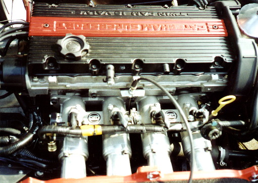
Below is a picture of the individual TBS as fitted to Tor Atles Caterham, they retain
the original fuel rail, injectors and fuel pressure regulator.
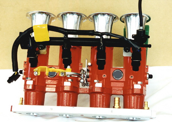
Dual bodies - type ‘TB’ and ‘TH’
Dual throttle bodies (which are fundamentally similar in layout to DCOE Webers) are a less expensive but still very effective solution. These are manufactured to fit wherever a pair of Webers will. All you need is a suitable manifold and they bolt straight on, they can also use Weber air filters etc. The bodies have pockets for mounting the injectors and come complete with fuel rails. The manifolds I have seen that are designed for Webers do not line the bodies up particularly well with the inlet ports since the flanges are spaced 90mm apart and the ports spacing is 88mm. However the manifold we are currently working on lines up almost perfectly with the ports, the outer barrels are only .5mm off the centre line of the port. The dual bodies correctly aligned offer virtually identical function to the individual bodies but are significantly less expensive. These dual bodies come in two types, ‘TB’ which are 118mm long and ‘TH’ which are 83mm long. The manifold we have designed also allows you to retain the existing fuel rail, pressure regulator, throttle potentiometer and injectors and makes a very effective solution. You will need a throttle linkage however and if your expected output is greater than 200BHP, some larger injectors. The injector position with these bodies is a good compromise giving a good transient and good power.


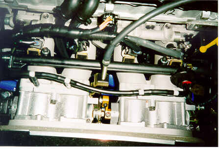
The Picture below shows twin Jenvey TB throttle bodies on the inlet manifold designed by Bernard, it has CNC machined flanges and tapered runners. The manifold includes an air gallery to allow for the air stepper motor control for the ECU, the spacing of the bodies is virutally perfectly aligned with the inlet ports. The standard K series fuel rail and integral pressure regulator is shown fitted.
Guide price for this type of system is around £550.
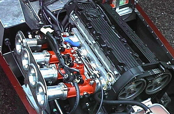
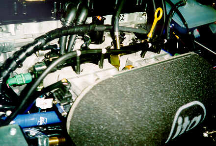
Below is a photograph of the dual Jenvey TB throttle body installation on a Caterham 1600cc K (Johnty Lyons car) the ITG twin airfilter has been removed. The manifold used is the one of our own manufacture which has provision for the idle control valve.
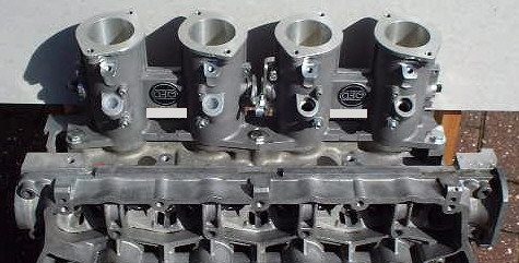
Direct to cylinder head dual bodies
Jenvey have recently started to produce dual throttle bodies which bolt directly the
the 'K' series cylinder head, the barrel spacing is the same as the port spacing on the
head so they offer perfect port alignment and also do away with the need for a manifold.
These are absolutely ideal for the engine and with a little modification and some small
brackets can take the standard fuel rail pressure regulator and injectors. They are 42mm
in size which is adequate for over 240BHP. They offer the simplest, cheapest and most
suitable induction system for the 'K' series engine. As cast they need matching to the
inlet port shape. If they had been available a year ago we most certainly would not have
developed our manifold for the dual TB type bodies. Currently they are priced at around
£425 per pair although that includes the fuel rails which are in fact redundant if the
original fuel rail is retained so the price will probably come down a little and I know
that some 'K' owners have negotiated a discount from QED. I arranged a bulk purchase of
these for a group of owners a few months ago and managed to negotiate a substantial
discount for quantity.
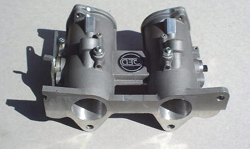
Shown below is a picture of a pair of the
bodies attached to a 'K' cylinder head, the only modification necessary is the mounting of
the water jacket takeoff on the front body.
Target price for this system is £400 +VAT
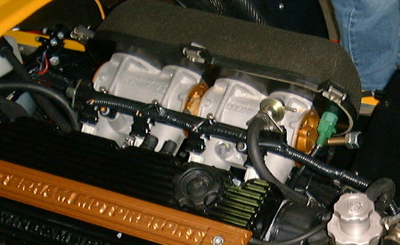
The photo below shows the DTH bodies installed on Rob Walkers immaculate self modifed
Caterham, he has retained the original fuel rail / injectors and integral pressure
regulator.
Cold airbox kit for direct to head
bodies
To complement the direct to head throttle bodies Bernand Scouse
has produced a complete cold airbox kit to fit the Lotus Elise / Exige and the Caterham
seven which allows retention of the standard fuel rail and pressure regulator, or fitment
of the Jenvey Fuel rail without needing spacers. it contains everything you need including
the airbox, a throttle linkage, trumpets, backplate, trunking , large Pipercross cone
filter and all fixings, it works out around half the cost of the equivalents. Below is a
photograph of the Elise airbox kit fitted to the DTH bodies, it could be adapted if
necessary to fit individual TBs or other types. The details of the kit are shown below the
picture. The Caterham version has the air pickup facing in the other direction and has
mouldings to clear the chassis member and clutch cable but is otherwise identical.

The kit is designed to fit onto QED, Lumenition or Jenvey direct
to head throttle bodies but could be made to fit individual bodies.
The main features
Complete kit, includes air box, air filter (Elise/Exige version only), GRP
trumpets , backplate fuel rail mounting, throttle linkage bracket, trunking and all
fixings required.
Enables the standard K series fuel rail, fuel pressure regulator and injectors to be used
without needing an external pressure regulator, which is adequate for engines up to about
210 BHP. Can also be used with the Jenvey fuel rail with minor modification, and does not
need the 20 mm spacers, saving over £80.
In the Elise/Exige installation, ducts cold air from the wheel arch intake directly
to the engine and only intrudes 10 mm into the boot space.
Appearance is excellent. and it can be removed in a couple of minutes.
The kit consists of
Price for Elise/Exige kit £290,
Price for Caterham kit £235
Please add £12 for post and packing.
If you want one please send a cheque to:
Bernard Scouse
12 Cleeve Way
Fivewells Lodge
Wellingborough
NN8 2RT
Phone 01933 224330
VHPD Induction system
This system uses the dual throttle bodies from the KV6 engine and a rather tortuous manifold, at the time of writing I don’t know whether this can be purchased separately. It is shown below; note the turns in the manifold runners and the injector position. There is also a long interconnected vacuum take off from the top of the bodies which is more clearly visible in the second photo'.
R500 Barrel throttle bodies
The R500 engine uses roller barrel throttle bodies which minimise
obstruction and drag in the inlet tract, these represent pretty much the ultimate in
induction systems but are pretty expensive, Below is a photo which shows them in situ
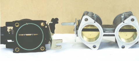
The picture below shows the standard throttle body alongside a twin Jenvey TH throttle body, normally two of these TH bodies are fitted.
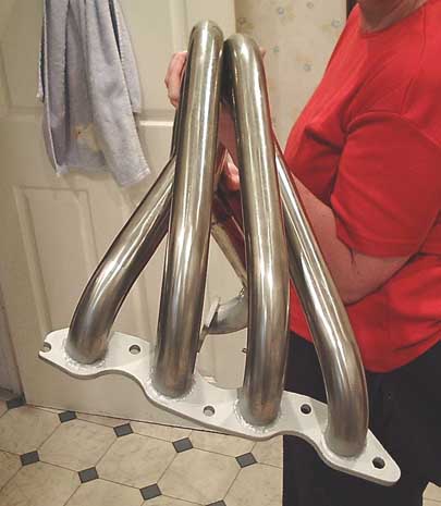
It is important not to underestimate the affect a properly designed exhaust can have on an engine, the stock manifold that comes with the K series as installed in the Elise is pretty awful, having very short primaries and a lot of welding clag in the inside of the manifold flange, the very least you should do with one of these is to fettle away the weld build up inside the manifold. Some of the Caterham manifolds are also very short on the primaries as are the manifolds which come with the K series as installed in its original Rover home.
Rolling road tests have shown that the best
configuration for the 1.6/1.8K series is a 4-2-1 manifold with 30-32 inch primaries of
1.5inch diamter and 10-12 inch secondaries of 1.75 inch diameter culminating in a 2.25
inch system, this setup brings large gains in the low and mid range torque without
affecting top end power. Long 4-1 manifolds can give a small improvement at the top end at
the expense of torque lower down. One Caterham owner who changed from the short 4-1
standard Caterham manifold to a long 4-2-1 custom made manifold saw an increase of 30ft/lb
at one point in the rev range and an increase of 20BHP on the peak power figure, this was
on an engine with modifed VVC head, DTH bodies, 835 cams and M3D engine management, the
improvement made was solely down to the manifold.
There are a number of people who can supply or manufacture a manifold for your
engine, QED make an excellent one for the Elise, Exhausts by Design and Powerspeed have
both made excellent manifolds for Elises, Exiges, 340Rs and Caterhams. Given the choice I
would always go for stainless steel, even though it is more expensive it is more durable
and attractive on the eye.
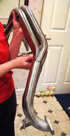
Shown below is the EBD (exhausts by design) 4-2-1 manifold for the Elise/Exige, it is
made in stainless steel and costs £350 It's been proven to work extremely well on the
dyno.
As far as the exhaust system goes there are even more possibilites, quite often the
standard exhaust systems fitted are quite poor and restrictive, a decent after market
straight through absorption only system is a better bet but be wary of noise levels. If
you can, buy a system which has a repackable silencer preferably in stainless steel.
Bottom end
Pistons seem to be the first Achilles heel of the engine, excessive (>7700) RPM can cause piston failure on the more powerful engines. Tor Atle's Superlite engine (around 200BHP) with a rev limit of 8000RPM had one piston completely fail and on subsequent inspection 2 of the remaining pistons had fractured lands between the top and second ring. It is a short route from there to complete failure. I am currently rebuilding his engine with a new liner and Omega forged pistons. Apart from the one liner damaged by the broken piston the liners show no sign of any problem. I would recommend that if you are producing and engine with > 180BHP or using more than 7700RPM then forged pistons would be a wise investment these will happily run in the standard liners, just have these glaze busted/honed first.
If you want to see the damaged sustained to the standard pistons and have a look at a forged Omega replacement click here.
The two 1.6 Superlites with 740 cams that are
limited at around 7800 have shown no problems so far, nor has Bernards Elise with a limit
of 7800 and 190+BHP. There is undoubtedly a liner problem with BHP > 200 and higher RPM
due to stress risers in the standard liner. Jim Currie can offer a solution to this
problem, QED cab also supply a steel banded liner which should prove stronger in use.
Brodie Brittain produce stronger liners which need the block to be machined to fit. They
also do liners which need no machining with special pistons, these drop the bore size and
therefore capacity by a small degree. Omega and Arias can supply pistons, Roger King and
QED can supply these, they are currently £425 +VAT and include rings. Although I have yet
to see a broken rod but they are certainly not indestructable, if very high RPM is
envisaged then they would be a wise choice especially on the 1.8 where rod angle is much
more pronounced. Steel rods can be supplied from Arrow Precision, steel cranks from Doug
Kiddie.
For the ultimate bottom end Brodie Brittain do a number of modifications which were
originally developed for the turbo conversion, these involve replacing the sandwich plate
at the bottom of the engine with a steel equivalent, machining the block and head to
accept much larger studding to replace the through bolts and replacement of the liners
with stronger equivalents. The block modifications eliminate a lot of the flexing of the
block assembly which is usually a pre-cursor to failure. If you couple these modifications
with a steel crank, steel rods and forged pistons you get as near to an unbreakable
combination as possible.
VHPD
The VHPD uses a tuftrided crank which although no stronger is more resistant to wear
and fatigue, it also utilises forged pistons and graded liners, the cams used are the
Piper 872 grind with solid followers.
R500
At the moment I dont have details of the construction of the R500 bottom end, but
considering its extended RPM range and price I would expect to see a steel crank and rods
together with forged pistons and selected or improved liners. The cams used are the
ubiqitous Piper 835/1227 profiles and the head is fully modifed but with standard sized
valves.
Lubrication
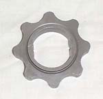
Oil pump
The oil pump on the K series has plenty of capacity and
doesn’t usually give any problems relating to sticking relief valve or volume of
delivery. In some of the very high revving engines there have been reported failures of
the pump rotor which is only sintered material. Replacement steel rotors are available
from QED which eradicates the problem of rotor breakage.
Steel pump rotor
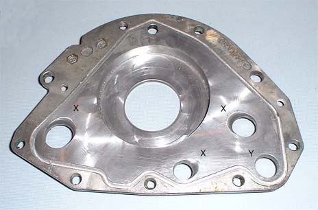
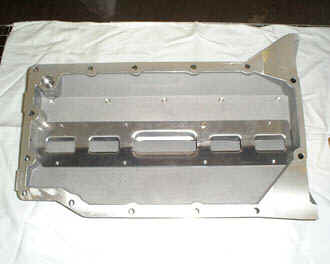
Modifying the oil pump
If you have the pump off the car at any stage it is worth removing the
backplate and ‘flowing’ the oil-way drillings in and out of the pump, At the
point where the oil enters and leaves the pump it has to cross a sharp 90 degree machined
edge, easing this edge to a smooth contour as shown in the photograph of Peter Carmichaels
backplate below should improve oil flow through the pump considerably. The edges of the
holes marked ‘X’ have been heavily radiused, note the direction of the radius is
in line with the direction of oil flow, the hole marked ‘Y’ has not been
touched.
The standard wet sump set up is generally OK for road use although those engines
fitted with VVC heads either with or without the VVC mechanism retained do suffer from oil
retention in the head, especially when installed at an angle as in the Caterham
installation. make sure you keep your eye on the oil levels. some engines suffer with oil
aeration which can cause the hydraulic tappets to rattle, the cuase of this is
pulverisation of the oil and the drawing of air through the oil pump creating an
emulsified oil/air mix. The K series was designed with transverse installation in mind,
fitting it in a fore-aft installation is not without its problems with the engine
suffering badly from oil surge where the oil is moved away from the pickup by the lateral
'G' forces generated when cornering hard. This is especially significant when taking part
in track days.
There are a few possible solutions to the problems associated with oil surge and if
you are serious about using your car on the track then you should consider them carefully,
I have seen quite a few good engines ruined for lack of consistent lubrication.
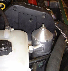
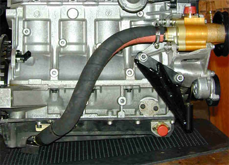
Apollo anti cavitation system
This is essentially an oil reservoir which is designed to de-aerate the oil, it holds some
extra oil capacity and is downwind of the pump so acts as a temporary reservoir of oil for
those occasions when the oil pump might not be picking up oil. Not a complete solution but
a relatively inexpensive half way house towards the efficacy of a dry sump system. The
p;icture below shows an Apollo tank as fitted to a 1.8K Caterham seven.
Accusump
The accumsump is an oil accumulator which holds a volume of pressurized oil for when the
oil supply is interrupted, it's capacity is fairly limited so it will only cope with
momentary lapses in supply. Once again this is not a complete solution.
Dry sump system
A dry sump system stores the engines oil supply in an external tank which is designed to
resist the affects of surge. The engines sump as its name suggests is designed to stay oil
free with all the oil being removed by one or more 'scavenge pumps'. The oil scavenged is
returned to the dry sump tank where it is plumbed to either the original oil pump, or to a
replacement pressure pump. The dry sump tank usually has much greater capacity than the
sump and is immune to surge, provided the scavenge pumps can do an effective job of
emptying the sump then the system should affod a high degree of protection against oil
supply interruption. The system for the Caterham uses a tank which is quite neatly
integrated into the wasted space in the bellhousing, this does limit the tanks capacity a
little.
Some sytems use a single scavenge pump removing oil from a single point in the dry
sump pan, others use multiple scavenge pumps which pick-up from more places and are less
affected by surge, these are normally know as two or three stage pumps depending on the
number of scavenge and pressure pumps. The Caterham dry sump installation relies on a
single stage scavenge pump driven by a belt and pulley and uses the standard oil pump. The
belt and pulley arrangement could be a bit vulnerable, several owners have now fitted
microswitches to give warning if the belt form the scavenge pump comes off.
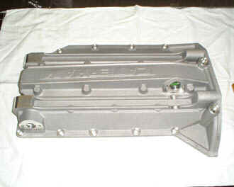
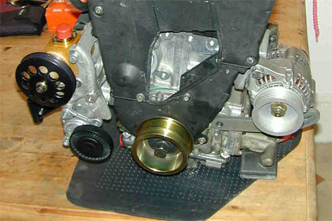
Caterham dry sump pan
Caterham 'gold' scavenge pump
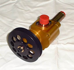
As installed on K series
Oil temperature
Oil temperature can be a problem on some highly tuned engines, consider 110 degrees to be
an absolute maximum, if your oil goes beyond this temperature then you have a problem
which needs to be controlled. There are two common possible solutions.
Oil cooler
An oil cooler is simply a radiator for the oil which functions in a similar manner to the
radiator for the cooling system, the plumbing in includes a sandwhich plate by the oil
filter which diverts the oil from the pump through the oil cooler radiator (which may have
a thermostatic valve to prevent over-cooling) and then back to the engine, these are fine
if you have room for the installation and a position for the oil cooler radiator where it
can exposed to a cold air stream.
Oil/water intercooler
An oil/water intercooler uses the engines cooling system to dissipate excess heat
from the oil. Provided the cooling system has sufficient capacity (and it generally will
have) then this is a better option, not only does it keep the oil from overheating, it
also warms the oil from cold start. The water in the cooling system will heat up very
rapidly and will pass some of this heat via the intercooler to the oil reducing the oils
warm-up time significantly. Some of these uses remote intercoolers and require plumbing
from a sandwich block at the oil filter housing and from the cooling system, other more
compact types are integrated with the sandwich block at the oil filter housing and only
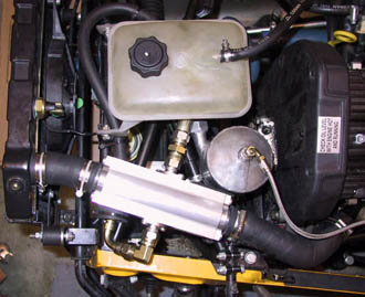
require plumbing from the coolant. The Laminova heat exchanger supplied by Think
Automotive is the remote type and is ideal for the Caterham , it can be plumbed in with or
without a dry sump system.
Laminova heat exchanger on dry sumped Caterham SLR
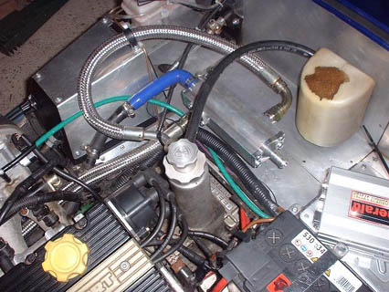
And plumbed in with an Apollo tank via
the radiator top hose
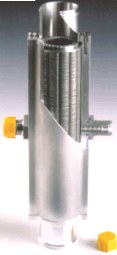
Selection of
tooling for head modification
If you are considering modifying your own cylinder head then it’s worth
acquainting yourself with the tools and techniques used to do the work. For an aluminium
cylinder head like the K series you will need some rotary carbide burrs to remove the base
material from the head. Most of this will be aluminium but some will be iron and steel so
general purpose burrs which are cross-cut or diamond pattern cut are the type to use. To
work the head you will need a good quality variable speed drill with an extension mandrel
for the bulk of the porting work and a high speed die grinder for opening the valve seat
inserts and for cutting back the valve guides.
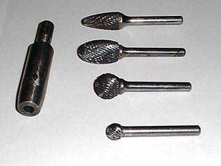
There are three main shapes of burr required for porting, large oval for general porting
work and working round the valve throats, large ball for removing the guides and bosses,
small ball for refacing the combustion chambers and large rounded tree for opening up the
valve seat inserts. A long flame shaped cutter can also help with the straight part of the
port tunnels and the throats on VVC heads but these can be very expensive. The picture
below shows some example cutters together with an extension mandrel for mounting in a
drill, using an extension has a number of advantages, reach and visibility being the main
two.
You cannot really run these cutters at higher speeds (> 2000RPM) when working
aluminium or they quickly clog up and overheat. Removing the snags of metal from the
cutter blades is then a tedious task that can only really be done when the cutters have
cooled. To prevent this problem it’s best to run the cutters at high speed only when
working on the steel components in the head, I.E. the valve seat inserts and guides. When
working on aluminium always run the cutters at a relatively slow speed in an electric
drill with a drill extension mandrel as shown below. This will minimise the tendency for
the cutter to become clogged. The speed of stock removal is still very good and with
regular cleaning of the cutter and removal of the stock/swarf you can make good progress.
If you can use an old hoover to extract the stock as you cut, so much the better.
It is best to cover the cutter in a dry lubricant before commencing work, tallow or a
PTFE based bike chain lubricant will do the job, this inhibits clogging and makes removal
of any snags of metal much more easy. I find that a 3M scotchbrite nylon scourer is ideal
to remove the worst of the clogging from a cutter, more stubborn snags can be removed with
the tip of a craft knife of scribe.
You can buy cutters which are specifically designed for aluminium and have very wide
flutes. These can be run at very high speed and do not clog up. However these are
expensive and are not happy cutting steel so to justify the expenditure you need to be
planning work on a number of heads. There is a picture below of a group of ‘aluminium
cut’ carbide burrs, very effective they are too.
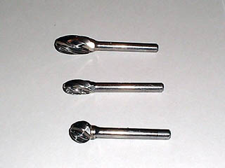
You can source these carbide burrs/cutters from a number of different suppliers and I have
had some success picking them up ridiculously cheaply by trawling through auto-jumbles at
kit car shows. However I have found J & L Industrial supply to be a convenient
supplier, they offer competitive pricing, have a wide range and allow credit card purchase
with next day delivery. J & L Industrial supply are on 0800 66 33 55
I have listed below the most popular/common carbide burrs for modifying a cylinder head,
together with their part numbers and prices from J & Ls catalogue. These are not
cheap, but are of exceptional quality and when properly looked after are good for twenty
or more cylinder heads so they can be sold on to another keen individual when finished
with. The GBC burrs are by Garryson, the BRC are by Interstate.
| Description | Size | Double cut | Diamond cut | Price |
| Oval | 12.5 x 22mm | BRC-55060K | BRC-34170L | £17.10 |
| 15.8 x 25.4mm | BRC-55080K | BRC-34180B | £27.80 | |
| 13 x 22mm | GBC-15700E | £21.12 | ||
| Rounded tree | 12 x 30mm | BRC-56060E | BRC-34205D | £16.90 |
| 13 x 25mm | GBC-19700C | £21.38 | ||
| Large balls (oo-err) | 12.5 x 11.4mm | BRC-54050K | BRC-34140M | £12.90 |
| 13 x 11mm | GBC-17700L | £14.52 | ||
| Small balls (tee-hee) | 6 x 6mm | BRC-54020L | BRC-33015K | £9.30 |
| Flame | 12.5 x 31.8mm | BRC-58030M | BRC-34280C | £28.60 |
| 15.8 x 36.5mm | BRC-58050H | BRC-34286E | £36.70 | |
| 13 x 32mm | GBC-15600D | £26.71 |
Below is a design drawing of a drill extension / mandrel for remote mounting of carbide
burrs and spira-band holders, it can be made of mild steel. One of these makes the job of
porting 300% easier mainly because you can see what you are doing and it is easier to
reach further into the ports without catching the drill chuck on the workpiece. If the
head you are working has longer ports or you need to work inside a long plenum then the
extension can be made longer.
To provide the correct finish on your masterpiece and for general smoothing work, you
can use abrasive spira-bands which are spirally woven tubes of material with abrasive grit
bonded to the outside. These are mounted on a rubber mandrel with a 6mm shaft that can be
put in the drill extension or the die grinder. They are very effective and are available
in various grits, the two most useful being 80 grit for subtle reshaping and blending and
120 grit for finishing off.
There are various other types of mounted abrasives such as cartridge rolls and cratex
points which can also be used if preferred. Personally I find the 12 x 25mm spira-bands
adequate for just about everything, although occasionally I need to use smaller 4 x 10mm
spira-bands in a Dremel for tight short-turns or combustion chamber corners. Below are a
couple of pictures of spira-bands with their respective mandrels, a couple of cartridge
rolls and a spira-band mounted in a drill extension. Generally speaking a Dremel or
similar simply doesnt have the power to undertake all the porting or smoothing work on a
cylinder head, but it may be useful for close up work like refinishing around the valve
seats
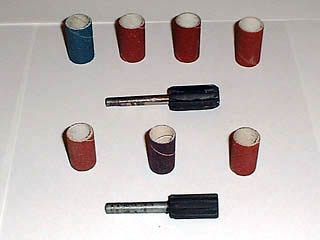
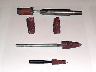
Spira-bands and their holders can again be bought from J & L Industrial Supply, I
favour the 13 x 25mm size which is just about ideal for the K Series port and throat
sizes, on larger ports and throats I use 15 x 30mm. The spira-band mandrels are designed
to expand at high RPM and thus grip the spira-bands. At the lower RPM available from a
drill they don’t expand so much and this can sometimes cause the bands to work loose
and fall off the mandrel. Because of this I generally buy 12.5mm ( ½ inch ) spira-bands
and fit them to a 13mm mandrel, this ensures a good tight fit. It is more economical to
buy the spira-bands in a length twice that of the mandrel and then cut them in two,
although this is fiddly it is worth doing since the longer bands are only 1-2 pence more
and it cuts the cost of the bands by 40%.
I have listed below the part numbers and prices of the spira-band mandrel and spira-bands
from J & Ls catalogue.
| Item | Size | Part number | Price | |
| Spira-band mandrel | 13 x 25 | GYF00635M | 5.72 ea | |
| Spira-bands | ½ by 1 | 80 grit | AWE-11080D | 0.14 ea |
| ½ by 1 | 120 grit | AWE-11120J | 0.14 ea | |
| (Cut these in two) | ½ by 2 | 80 grit | AWE-12100K | 0.15 ea |
| (Cut these in two) | ½ by 2 | 120 grit | AWE-12120D | 0.16 ea |
If the bands are fitted to the mandrel with a slight over hang of 3-4mm at the working end
it allows the end to deform a lot more easily around the more complex curves of the valve
throats and port, this gives a better finish and extends the life of the band.
The picture below shows my trusty Makita die-grinder, this is an electric die-grinder with
a 6 mm collet but will also accept ¼ inch shanked burrs (these can sometimes be had very
cheaply at auto-jumbles). It’s compact, light, easy to wield and was relatively
inexpensive to buy. It has no-load speed of 35,000 RPM, and to vary its running speed I
use a 10 amp variable power controller from RS components (part number 655-638) which
enables me to tailor the speed from as little as 100RPM (for combustion chambers) up to
the full speed. Alongside is a well used 3M pan scourer I use to clean the burrs and some
‘Finish line’ PTFE based bike chain lubricant I use on the burrs to discourage
clogging up.
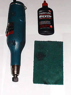
While porting the head it is very important to ensure that ports and valve throats
are opened to the correct size and that valve throats are entirely concentric with the
valve guides. To help check this I have a set of old valves turned down to a variety of
different sizes, this helps me to check at a glance when something is sized correctly. It
also allows me to ensure complete concentricity of valve throats as I open them out. Old
valves also have a role to play protecting the valve seats when the combustion chambers
are being refaced.
To turn some old valves to the required sizes I mount them in a drill which is
clamped safely in the vice, I then use an angle grinder to gently remove material from the
outside circumference of the valve while it is spinning. A similar method can be used to
modify old valves to act as blanks to protect the valve seats while modifying the
combustion chambers. In this case the material is removed from the valve’s seat to
allow the valve to sink into the seat in the head.
I use a similar method to put a 30 degree cutback on the back of exhaust valves. The
angle grinder leaves quite a rough finish which is reworked using an old cutting disk held
by hand followed with progressively finer abrasives. Always wear protective glasses when
doing any work with rotary tools or any work which produces swarf. I have a standing joke
about ensuring the casualty department of the local hospital is open before commencing
work. Despite precautions I have ended up with shards of metal embedded in the Schlera of
my eyes far too many times.
Below is one set of sized K series valves which I use when porting, the collection has
grown a little since this shot was taken. The first and second rows are for sizing and the
bottom row is a succession of ‘blanks’ for protecting valve seats. If you are
converting to big valve then you will have a complete set of valves that you can use to
make blanks.
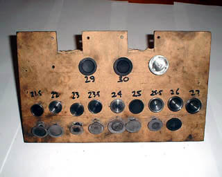
Modifying the ‘K’ series head.
General K16 head
Considering that the same valve sizes and similar porting are used on 1.4/1.6 and 1.8 variants of the K series engine, it is not surprising that the head in standard form is under-valved for the larger engines and has inadequate flow for high specific outputs. This is one reason why the characteristics of the engine in its various sizes are as they are.
The inlet valves are 27.5mm in diameter, the exhausts 24mm, for the 1800 even in otherwise standard form, the valve sizes need to be around 29-30mm on the inlets and 25-26mm on exhaust. The porting is inadequate for the current valve sizes and gains can be had by simply porting the head, modifying the valves across the seat and paying close attention to the seat inserts. Substantial gains can be had here especially on the larger engines, even when retaining the standard valve sizes. The valve seat inserts are generous enough to allow a larger valve on both inlet and exhaust provided that the throats, seats and ports are sized accordingly.
The combustion chamber is typical of a 16-valve engine and has little valve shrouding; the port orientation is not ideal because of the way in which the inlet and exhaust tunnels are so sharply siamesed at the manifold face.
The valve seat inserts are not particularly well lined up with the valve throats and this is not uncommon with inserted heads. The valve guides and bosses offer a severe restriction to flow in the valve throat area, which is already less than adequate.
Inlet tracts
An initial look at the head shows some problems in the port design and size. Unlike most 16-valve heads, the port entry is round; this causes the flow to diverge to each valve in turn and causes the incoming mixture to bounce off the cylinder wall. This is good for swirl and therefore economy and emissions, but not so good for volumetric efficiency, to improve this the valve throats need to be shaped to turn the mixture away from the cylinder wall so that it gets a straight shot at the cylinder. The port entry has plenty of area for the std valves at 34mm cross section, unlike the main port tunnels; these are too small for the current valve sizes. They are approximately 19mm in cross section and should be at least 23mm. The enlargement of the port is the main factor in increasing volumetric efficiency. Material can be removed evenly from all sides of the port tunnel to achieve this if care is taken.
There is a 'step' on the top of the port where the port contour follows the underlying tappet bore, this is before the bifurcation where the port separates into the two tunnels this needs to be flattened as much as possible by removing around 1-1.5mm of material.
The valve guide and boss protrude quite a way into the port, once again worsening flow, these can be cut/ground away since there is plenty of guide length to support the valves without these bosses.
The valve inserts are poorly matched to the throat both on the short side and long side of the port. Where the port bifurcates into separate tunnels, the actual bifurcation is quite blunt where the port narrows, this can be cut back by a substantial amount, care is needed here since there is a water drilling down at a diagonal through the centre of this part of the port. At worst this can be sleeved or filled since the cooling on this side of the head is not as critical as the exhaust side.
The valve insert throat diameter is too small for the valve, and the seat is too wide for the valve. The insert throat is approximately 23mm, and should be nearer 25mm; the valve seat can be reduced to 1.2mm or so by blending the top of the insert out into the seat area using a radius. The valve throat area should be made at least 24mm in cross section and blended into the port tunnel. The short side of the port needs to be reshaped so that its radius is concentric with the opposite side of the valve throat. The outside wall of the valve throat area needs to be cut back to help the mixture turn towards the centre of the bore as it enters the cylinder to avoid a collision with the bore wall. The port shape should be oval, 23mm round and around 24mm high.
The inlet valves themselves are not too bad although the stems are wide in the port area, and the seats are too wide. Since the valve is two-piece it is unwise to modify the stems, however the back of the valve can be blended into the seat area using a radius rather than the current 30-degree cut.
Larger inlet valves
If you are contemplating fitting larger inlet valves to a head destined for a 1.4 engine be careful to ensure that the valves will not clout the bore walls, the largest inlet vsalve that can be fitted to the 1.4K head without modifying the liners with cut-outs is 28mm, the largest exhaust is 25mm. If you want to use larger valves than these then cut-outs must be made in the liner tops and the pistons tops.
Larger valves of 29.5mm can be fitted to the standard inserts provided the walls of the inserts are not left too thin, consider 25.5mm to be the maximum internal throat diameter, blending out to a seat around 1mm wide. The inlet tunnels will need opening to around 24mm wide by 25mm high, take material carefully from the roof and floor of the port to increase the cross sectional area. Keep an eye on the wall thickness here that can be gauged by measuring or feeling through from the waterways on the head gasket side of the head. The port entry needs to be enlarged by 2mm or so to 36mm for a 29.5mm inlet valve, take material carefully only from the port roof and top of the sides. The roof is the side nearest the top of the head when the head is fitted, the port entry only has to be enlarged till about 8mm inside the head, since the cross sectional area further in is adequate.
Valves larger than 29.5mm (VVC 31.5mm or even 32.5mm/33.5mm) will require the head to be inserted, with a corresponding increase in valve throat insert diameter to around 27mm. Port area needs to increase to 25mm round and 26mm high (consider this the maximum safe size) and port entry area to around 37-38mm again removing material from the port roof and sides only. Be wary at this size not to break through the casting. When opening the port for larger valves the waterway drillings down through the bifurcation will definitely need sleeving or blocking with 5mm tube or bar loctited/epoxied into position, there is a section on doing this below. The cooling on this side of the head is not so critical in fact the VVC/VHPD head does away with these drillings completely.
Exhaust tracts
The exhaust ports suffer from the same maladies as the inlet port, but more so. The port cross section is way too small at around 17-18mm; this needs to be increased to around 20-21mm removing metal equally around all sides of the port walls. The sharply siamesed port causes the exhaust flows to converge very rapidly and create turbulence at the main port exit. Once again the bifurcation can be cut back substantially but into a concave shape which will help to turn the exhaust as it meets the flow from the other valve, this will minimise the turbulence. Care must be taken here just as on the inlets since there is a similar diagonal waterway drilling down through the bifurcation, careful examination can determine where the port is at risk. The valve guide boss and end of the guide again protrude into the port and can be carefully reshaped to ease the transition from valve throat to port runner.
There is a large lump in the port roof which is much worse than on the inlet side, this again follows the form of the underlying waterway and can be reduced by 1-1.5mm, this improves the port shape quite dramatically, but great care must be taken to avoid breaking through. This is the main obstacle to the ports flow and causes the flow to break away from the port walls.
The port exit has plenty of area for standard sized valves, although once again it is round in section, careful shaping of the valve throats and port tunnels is required in order that the two flows from the exhaust valves don’t interfere with one another too much. There is merit in squaring off the corners of the exhaust exit which causes less disruption to the exhaust flow.
The valve throats are too small and need opening to around 21-21.5mm while retaining the port square cross section. The exhaust seats are too wide and can be reduced to around 1.6mm, the valve can have the inner edge of the seat slightly radiused where it meets the back of the valve. The outside edge of the face of the valve can be radiused also. The inserts do not match up well with the valve throats and port contour; again the edges of the inserts can be blended into the throat area. The short side of the port lines up particularly badly with the inserts leaving a very sharp edge this area need blending into a smooth radius which should be concentric with the opposite side of the valve throat area.
Larger exhaust valves
Larger valves of 26mm can be fitted into the standard inserts, these are not as large as those fitted to the VVC and VHPD heads but are still a big improvement over the std 24mm ones. The valve throats and throat area will need opening to around 22mm and then they need radiusing into a seat around 1.6mm wide The ports need enlarging to 22mm, removing metal from all around the port, their size increases gradually till it meets the port exit. Be very careful with the port roof where the 'bump' is since there is a waterway directly below. The port exit needs to be enlarged by 2mm or so to 36mm for a 26mm exhaust valve, take material carefully from all round the port walls retaining the square section of the port. The port exit can be squared off and only has to be enlarged till about 4-5mm inside the head, since the cross sectional area further in is adequate. Be careful to blend this in with the existing cross section.
Combustion chamber
The combustion chamber is similar to most pent roof heads; the only shrouding present is where the chamber meets the surface of the head in the corners of the chamber. Here the valves need un-shrouding by a millimetre or two, blending the area into the chamber wall. This is normally where detonation starts so care must be taken to get a good contour with no sharp edges. Bigger valves will require a modicum more of un-shrouding.This un-shrouding must not cause the chamber diameter to exceed the bore diameter at any point, be careful only to flare the chamber wall out 1.5-2mm or so.
Other than that just a clean up of the combustion chamber to remove any casting marks or sharp edges around the seat insert and to minimise any 'recessed' inserts is all that is required. A small radius imparted to the sharp edges of the combustion chamber will help prevent detonation.
There are two dead areas on either side of the spark plug at the deepest and widest part of the combustion chamber. On the VVC and VHPD heads these is filled in and radiused, on the std head they should be left untouched.
If the head needs has been modified in
accordance with the instructions above then it will need a skim of approx 10 thou to bring
the chamber volume back to normal, a further 10 thou will raise the CR by approximately .5
of one point. If you are retaining standard K16 pistons then this is recommended, if you
have forged pistons then it is wise to just remove 10 thou. Although the head is lacking
in stiffness experiences has shown that up to 30 thou can be safely removed.
Waterway
modifications
K series heads as they leave the factory are not always finished to the degree intended,
quite often the waterways are left quite badly fettled to the extent that the waterway
area is a lot less the the original production design. Since the K series has a very low
volume of coolant it is necessary, especially on the exhaust side of the head, to improve
the water passageways by opening to the maximum extent as originally envisaged by the
designers. The pictures below show a typical pair of exhaust waterways as the head left
the factory and the same waterways as modified. These modifications can substantially
improve the water throughput of the head and assist cooling. Both the inlet and exhaust
waterways can benefit in this way.
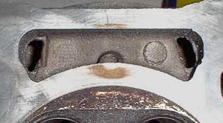
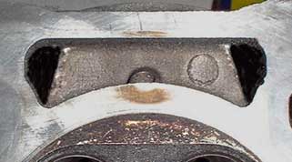
Blocking the inlet waterway drilling
The pictures below show 5mm aluminium bar being drifted into the inlet waterway drilling
to block the hole in preparation for porting. Without this bar in place it is not possible
to acheive the correct shape around the port bifurcation. Prior to insertion a centimetre
or so of heat resistant epoxy (Devcon Aluminium or J.B Weld) should placed in the hole and
a little spread on the end of the bar. The bar should be exactly 5mm in diameter and each
piece should be 42mm long with a very small chamfer on the leading end which should also
be cut off exactly square.
You may find that the drillings are slightly furred up or undersized by a small
margin, it is therfore advisable to clean the hole up with a 5mm drill bit, do not use a
drill but rather do the cleaning up by hand by turning the drill bit carefully in the hole
manually or with a brace and bit, be careful not the break the drill off in the hole. The
bar should be drifted all the way in until the end is flush with the top end of the
drilling hole. The head should than be turned so that the open end of the drilling is
facing downwards allowing the epoxy to form a sealing plug over the internal end of the
bar.
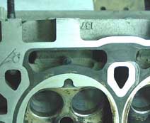
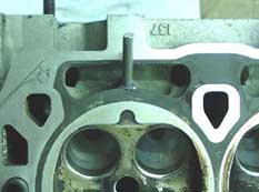
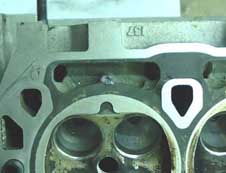
It is neither necessary nor desirable to block the exhaust drillings. If however you
break into one of the exhaust waterway drillings while porting, some 5mm OD aluminium tube
can be used to sleeve the hole, if you cannot source 5mm OD tube then it is
straightforward to drill a 3mm or 3.5mm hole down the centre of a short length of 5mm bar,
the sleeve can then be drifted into the hole with a little Loctite or epoxy to repair the
damaged section of waterway hole.
Modifying the VVC/VHPD head
General
The VVC/VHPD casting represents a significant improvement over the original K16 casting, it is fitted with larger inlet valves which are 31.5mm compared to the K16 27.5mm and large exhaust valves which are 27.3mm compared to the K16s 24mm. The inlet port line is raised by 3mm or so making the inlet port more downdraughted. In general both the inlet and exhaist ports are larger and the inlet side has modified waterways which allow the central bifurcation between the inlet valves to be minimised. The combustion chamber design has been improved by doing away with the dead spots and providing a smoother flow into the cylinder. The fitment of an unmodifed VVC/VHPD head to a 'K' series is a worthwhile modification and with suitable complimentary modifications can bring the output of the engine up considerably.
Light porting of the cylinder head with careful attention to the area around the vale seats and the combustion chambers can yield worthwhile results whilst retaining the standard valves. A small improvement can be had by using Paul Ivey's low profile waisted stem inlet valves. If you are going to the expense of buying new valves then it is probably worth buying the slightly larger 32.5mm inlets from Paul Ivey, these will fit the standard inserts with a little modification work. The standard exhaust valve size is adequate and the stock exhaust valves are of good quality; they seem to stand up to quite high RPM with no problems.
Like with the K16 the valve seat inserts are not particularly well lined up with the valve throats and this area needs attention. For some reason it is common for the inserts to be very badly recessed into the combustion chambers. The valve guides and bosses offer a severe restriction to flow in the valve throat area, because of the raised port line this is very marked with the guide boss and a smaller boss which covers the end of the follower bore protruding into the inlet stream.
Inlet tracts
An initial look at the head shows some problems in the port design and size. Unlike most 16-valve heads, the port entry is round; this causes the flow to diverge to each valve in turn and causes the incoming mixture to bounce off the cylinder wall. This is good for swirl and therefore economy and emissions, but not so good for volumetric efficiency, to improve this the valve throats need to be shaped to try to turn the mixture away from the cylinder wall so that it gets a straighter shot at the cylinder. The port entry has plenty of area for the std valves at 36mm cross section, the main port tunnels need some modification around the area of the valve guide boss and follower boss. The cross sectional size to aim for here is at least 27mm. With care the guide boss can be completely removed as can the follower boss although great care must be taken here to avoid breaking through the casting. The valve throat cross section should be around 27.5mm for standard valves and 28.5mm for the larger 32.5mm valves, the ideal shape here is like the inside of an egg cup, this can be acheived provided care is taken.
The valve inserts are poorly matched to the throat both on the short side and long side of the port and need to be remedied, the short turn especially is too blunt in section and needs to be flattened off to give the air a straighter shot down into the cylinder, the inner corners of the short turn need cutting back susbtantially to improve airflow past the bifurcation which should be minimised.
The valve insert throat diameter is too small for the valve, and the seat is too wide for the valve. The insert throat is approximately 26mm, and should be nearer 27.5mm (28.5mm for bigger valves); the valve seat can be reduced to 1.2mm or so by blending the top of the insert out into the seat area using a radius. The valve throat area should be made at least 27.5mm (28.5 for big valves) in cross section and blended into the port tunnel. The short side of the port needs to be reshaped so that its radius is concentric with the opposite side of the valve throat. The outside wall of the valve throat area needs to be cut back a little to help the mixture turn towards the centre of the bore as it enters the cylinder to avoid a collision with the bore wall.
The inlet valves themselves are not too bad although the stems are wide in the port area, and the seats are too wide. Since the valve is two-piece it is unwise to modify the stems, however the back of the valve can be blended into the seat area using a radius rather than the current 30-degree cut.
Larger inlet valves
Larger valves of 32.5mm can be fitted to the standard inserts provided the walls of the inserts are not left too thin, consider 28.5mm to be the maximum internal throat diameter, blending out to a seat around 1.2mm wide. The inlet tunnels will need opening to around 26mm wide by 27mm high, take material carefully from the roof and floor of the port to increase the cross sectional area. Keep an eye on the wall thickness here that can be gauged by measuring or feeling through from the waterways on the head gasket side of the head.
Valves larger than 32.5mm (33.7mm) will require the head to be inserted, with a corresponding increase in valve throat insert diameter to around 30mm. Port area needs to increase to 27mm round and 28mm high (consider this the maximum safe size) and port entry area to around 38mm again removing material from the port roof and sides only. Be wary at this size not to break through the casting. There is no material eveidence to suggest that there are gains to be had by fitting 33.7mm valves in preference to 32.5mm ones.
Exhaust tracts
The exhaust ports suffer from the same maladies as those on the std K16 head. The port cross section can be increased to around 22mm removing metal equally around all sides of the port walls, retaining the square nature of the port. The sharply siamesed port causes the exhaust flows to converge very rapidly and create turbulence at the main port exit. Once again the bifurcation can be cut back substantially but into a concave shape which will help to turn the exhaust as it meets the flow from the other valve, this will minimise the turbulence. Care must be taken here just as on the K16 head since there is a diagonal waterway drilling down through the bifurcation, careful examination can determine where the port is at risk. The valve guide boss and end of the guide again protrude into the port and the outside edge of the guide and its boss can be carefully reshaped to ease the transition from valve throat to port.
There is a large lump in the port roof which is much worse than on the inlet side, this again follows the form of the underlying waterway and can be reduced by 1-1.5mm to try to straighten the line from the throat to the port exit, this improves the port shape quite dramatically, but great care must be taken to avoid breaking through. This is the main obstacle to the ports flow and causes the flow to break away from the port walls.
The port exit is slightly short on area for standard sized valves, and once again it is round in section, careful shaping of the valve throats and port tunnels is required in order that the two flows from the exhaust valves don’t interfere with one another too much. Enlargement of the port exit should be confined to the roof of the port. There is merit in squaring off the corners of the port exit to a degree and opening the port roof up a little at the exit face.
The valve throats are a little too small and need opening to around 23.5mm. The exhaust seats are too wide and can be reduced to around 1.6mm, the valve can have the inner edge of the seat slightly radiused where it meets the back of the valve. The outside edge of the face of the valve can be radiused also. The inserts do not match up well with the valve throats and port contour; again the edges of the inserts can be blended into the throat area. The short side of the port lines up particularly badly with the inserts leaving a very sharp edge this area need blending into a smooth radius which should be concentric with the opposite side of the valve throat area. Quite often the valve seats are not cut to the full widht of the valve but are around.75mm undersized, this in turn limits the maximum possible size of the valve throats, it is worth ensuring that the seats in the head are cut wide enough to accomodate the full size of the valve, then the throats can be opened without compromising the integrity of the seat. It is beneficial to have a small radius or 60 degree cut leading into the valve seat.
Standard exhaust valve (VVC) and one modifed with 30 degree cutback, this cutback
reduces the seat width to around 1.5-1.6mm
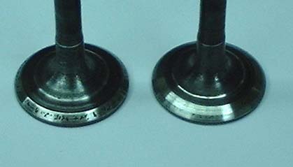
Standard exhaust valve (VVC) and one with radiused/modified edge
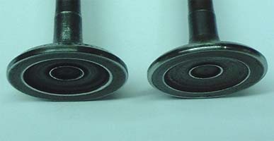
Exhaust seat in head (VVC) with 60 degree cut before valve seat
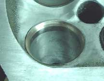
Larger exhaust valves
As yet I have not fitted larger exhaust valves to a VVC/VHPD head but the inserts would easily take a valve of 28.5mm with a corresponding increase in throat size and port area. Since a modified exhaust port with standard 27.3mm valves flows over 110CFM larger valves are probably not necessary.
Combustion chamber
The VVC style combustion chamber represents a significant improvement over the K16 as
it does away with the two 'dead areas' at the sides of the chamber.
The combustion chamber is similar to most pent roof heads; there is very little shrouding, only when fitting larger valves do the combustion chambers need reshaping a little in the corners. Here the bigger valves need un-shrouding by a millimetre or two, blending the area into the chamber wall. This is normally where detonation starts so care must be taken to get a good contour with no sharp edges. This un-shrouding must not cause the chamber diameter to exceed the bore diameter at any point, be careful only to flare the chamber wall out 1.5mm or so.
Other than that just a clean up of the combustion chamber to remove any casting marks or sharp edges around the seat insert and some cutting back of the chamber surface to minimise any 'recessed' inserts is all that is required. A small radius imparted to the sharp edges of the combustion chamber will help prevent detonation.
If the head needs has been modified in
accordance with the instructions above then it will need a skim of approx 10 thou to bring
the chamber volume back to normal, a further 10 thou will raise the CR by approximately .5
of one point. If you are retaining standard K16 pistons then this is recommended, if you
have forged pistons then it is wise to just remove 10 thou. Although the head is lacking
in stiffness experiences has shown that up to 30 thou can be safely removed.
With ceretain cams that have more than 10mm lift, such as the 1227/835 and BP320
grinds the tip of the lobe of the cam can foul the cylinder head at the top of the
follower bore, this happens if the base circle is larger than 28mm and the lift is greater
than 10.5mm. It is necessary to fettle this area lightly to provide clearance and this is
best done while the head is being modified. Speaking from experience, you dont want to
find this out when the head is fully assembled with the cam shimming complete since it is
then necessary to completely strip the head to undertake the necessary work, below is a
photograph showing where the head has to be fettled, this may need to be done on both
sides of each follower bore and on both the inlet and exhaust cams
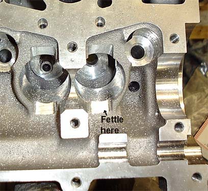 .
.
Replacing valve guides
The guides as fitted to K-series heads are of acceptable quality in standard applications,
but when valve lift and acceleration are high they can wear at a fairly rapid rate. When
the heads are modified the guides are often shortened to conform to the shape of the port,
this is the only way to acheive the correct port shape without removing the guides.
Sometimes this can lead to rapid guide wear which in turn can cause valve seat / stem
problems and leakage from the valves. To help longevity it is worth replacing the guides
with better quality Colisbro equivalents which are available from REC (Paul Ivey), these
are half the price of the standard production guides and are much more durable, they also
run closer tolerances. If the head has been modified by removing the guide boss it can be
beneficial to taper / bullet the end 10mm of the inlet guides at an angle of about
70 degrees (see drawing below). The new material is much more hardwearing and if the new
guides are kept full length the longevity is vastly improved. The seats will need to be
recut to match the new guides so if you are replacing the guides at the same time as
porting, do not cut /trim the new seats until after the new guides have been fitted
because they are unlikely to be entirely concentric with the old guides. Make sure that
you leave the old guides in when porting so that they can be used to help assess the
concentricity of the valve throats as you open them up.
To remove the old guides you need to heat the head up to around 150-175 degrees Centigrade
(gas mark 4), by placing the head in a normal oven for about 30 minutes at this
temperature. Ensure all the oil is washed off the head and that the stem seals are
removed. Once the head is at this temperature the old guides can be knocked out easily
with a suitable drift (see drawing above) with the head on a flat surface. Ensure that the
outside diameter of the new guides being fitted is the same as the O.D. of the guides
being removed. Before fitting the new guides they should be placed in the freezer while
the head is being heated up to 150-175 degrees. The guides should protrude 6.3mm from the
spring seat when fully home, a suitable drift can be used with a spacer in order to drive
the new guides home, ensure that the guides are driven absolutely perpendicularly to the
hole, a sleeve can be made to slot into the follower bore to assist this (see drawing
below).
Fitting the rotor arm spigot to the inlet cam
If you are replacing the inlet cam on an engine equipped with a distributor
cap and single coil then you will need to fit a rotor arm holder in the end of the cam in
order that the distributor functions correctly. The holder can be bought from Rover for
around £6 and is identified by its part number (NJJ10001). The picture below illustrates
the required radial position of the insert WRT the lobes on the cam, if this position is
incorrect then the engine may run improperly. The picture shows the cam resting naturally
on a flat surface with the cam lobes for cylinder 4 exactly vertical. Note the angle of
the ‘flat’ on the rotor arm insert is around 10 degrees to the vertical when the
cam is in this position. Sometimes the end of the insert that fits inside the cam is a
little tight and requires a larger chamfer and some light fettling to get it started. Once
it is started it can be knocked in with a suitably sized deep socket, it should be knocked
home until the bush part of the insert is flush with the end of the cam
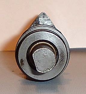
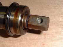
Retention of distributor cap
with VVC head
When using a VVC head on an a K16 engine which previously had a
distributor cap fitted it has previously been necessary to convert the engine to wasted
spark using a twin coil pack and individual leads with appropriate changes to the engine
management. It is possible however to drill and tap the end VVC blanking plate to accept
the original distributor cap and fit a rotor arm holder to the end of the inlet cam and
save some expense and aggravation. When you offer the cap up to the blanking plate you
will see that it will sit in a natural position with the two holes offset downwards and
lining up in a horizontal position. This is in a slightly rotated position (35 degrees
anti-clockwise) from on the original head and requires the rotor arm holder in the end of
the cam to be fitted rotated 35 degrees anti-clockwise to compensate. This makes a
perfectly satisfactory solution and allows retention of all the original ignition
componentry.
The rotor arm insert needs to be driven 3mm further into the end of the inlet cam
than normal and the plug leads need to have the centres of the leads pulled 15mm further
down towards the plug through the plastic rigid section, if you lubricate the plug lead
where it enters the plug end section then this can be done fairly easily.The picture below
shows the original cap mounting on a K16 head, the cap as fitted to the VVC blanking
plate, and the VVC blanking plate as drilled and tapped (M6 x 1 thread) for the cap.
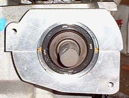
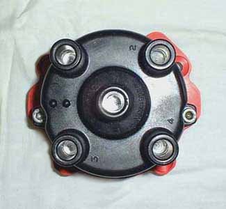
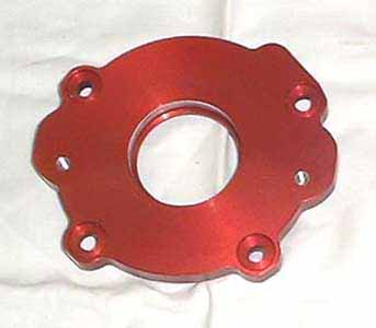
Comparative positions of rotor arm spigot for standard and VVC
inlet cams
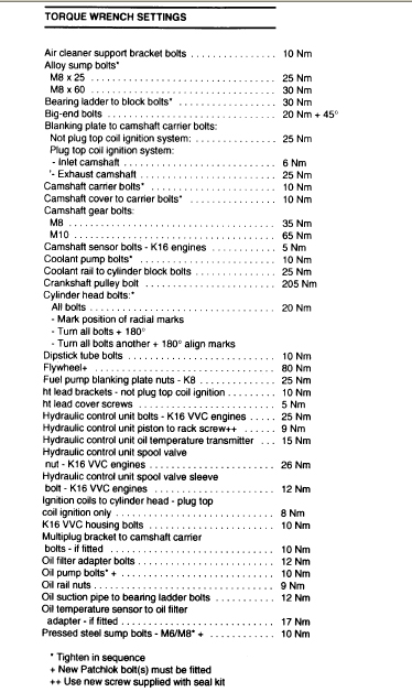
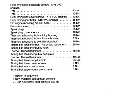
Flowbench Comparisons
To see the flowbench results on a standard K16 head, a VVC/VHPD head and some modified big valve K16 and VVC heads click here.
Rolling Road results
So far two of the cars with modifed 1600cc
engines have been on a rolling road, Paul Ransons and Johnty Lyons Caterham Superlites
(standard output 118BHP) which had already had the 'supersport' kit fitted (138BHP) were
fitted with identically specified modified big valve heads prepared by myself (29.5mm
inlet , 26mm exhaust), Piper 740 cams using solidified standard hydraulic followers and
Jenvey dual TB throttle bodies on manifolds of our own manufacture. This combination gave
a very satisfying 179BHP @ 7600 and 128ft/lb torque between 6200 and 6600 for Pauls car
and a nearly identical 178BHP with a little more low down torque for Johntys car. Both
cars used Emerald M3D 'K' engine mangement ECU and were mapped on Dave Walkers rolling
road at Emerald.
For comparative purpose Dave Walker also ran two other Caterhams up on his rolling road on
the same day, a 1600K Supersport and an 1800K Supersport, the 1600SS made around 140BHP
with the 1800 making around 135BHP but more low speed torque. This gives testimony and
credence to the accuracy of the rolling road since the supersport conversion is rated at
138BHP.
The overall cost of the conversion including rolling road mapping, gaskets sundries etc
was around £1500. This output is not far short of the VHPD engines output and is from
only 1588cc. Needless to say the cost comparison between a VHPD engine and a converted one
is an interesting one. As is the comparison between the Supersport conversion and this one
since these modifications can be made to a basic non SS engine. I would expect Tor Atles
Superlite to give 10 to 15BHP more since it has more extensive head mods (VVC sized
inlets) and more extreme cams (Piper 835). Bernards Elise head has the same spec as
Tors, but 740 cams, it is however an 1800cc K engine.
Below is a plot of Paul Ransons power and torque curves extracted directly from the rolling road. The fluctuations in torque between 1100rpm and 2000rpm are due to abberations in the coast down tests at such relatively low speeds.
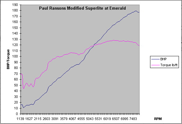
Elise Rolling road session
We now have the rolling road results for
Bernards Elise (1796cc) it was fitted with a modified big valve head prepared by myself
(VVC sized 31.5mm inlets, 26mm exhausts), Piper 740 cams using solidified standard
hydraulic followers and Jenvey dual TB throttle bodies on a manifold of our own
manufacture. It used a home made airbox and an aftermarket exhaust. The standard
(horrible) exhaust manifold was retianed but was fettled by myself. This combination gave
194BHP @ 7600 and 142ft/lb torque @ 6400 at a recent Lotus Elise rolling road 'shoot-out'
at Emeralds rolling road. The engine management system was the Emerald M3D'K' ,and the car
was mapped on Dave Walkers rolling road at Emerald. For what it's worth the standard
engine before modification gave 122BHP on the same rolling road which is not far off the
factory estimated output of 118BHP, this gives credence to the accuracy of the rolling
road.
Following this a VHPD Caterham was run up on the same rolling road and made 181BHP, after
examining the power and torque curves it was clear that the power run was interrupted just
before peak power. I would estimate that had the misfire which caused the early finish not
taken place it would have made around 190BHP. Its power and torque curves are shown below
that of Bernards Elise.
Below is a plot of Bernards Elise power and torque curves extracted directly from the
rolling road. Bernard engine retains the standard cat and short exhaust manifold.
Caterham VHPD Rolling road session
Below is a torque and power graph from a VHPD
engine in Graham Ridgeways Caterham which is the car which took the record as the fastest
road car lapping the Nurburgring, it is an interesting comparison. The VHPD uses the VVC
style head, Piper VHPD cams (280 degrees) and dual twin throttle bodies. The cams are
hotter than the ones used in Beranrds Elise and Paul/Johnty's Caterhams
Steve Butts Elise Rolling road session
Steve Butts Elise proved to be one of the
better road conversions, making a creditable 206BHP after a bit of playing with the cam
timing, it was fitted with a modified big valve head prepared by myself (29.5mm
inlets, 26mm exhausts), Piper 740 cams using solidified standard hydraulic followers and
Jenvey dual TB throttle bodies on a manifold of our own manufacture. It used a home made
airbox and a 4-2-1 manifold which was custom made, it was also fitted with forged pistons.
This combination gave 206BHP @ 7500 and 153ft/lb torque @ 6100 at Emeralds rolling road.
The engine management system was the Emerald M3D'K' ,and the car was mapped on Dave
Walkers rolling road at Emerald. It is a great pity that the car was destroyed by
fire before Steve had a chance to use it in anger. Steve now has a VHPD engined Elise and
will be embarking on some modifications before long
Mike Bees' 1700 Caterham
Superlite
Below is the torque and power curve from Mike
Bees K series Caterham Sprint car. The engine is a proper competition prepared unit using
a steel crank and rods specially made to bring the capacity to 1700cc, it also uses forged
pistons and stronger liners. The cams are Piper 835 exhaust and Piper 290 inlet, with
solid followers, it uses Jenvey single throttle bodies on a Jenvey manifold , a Caterham
long 4 into1 exhaust, an Emerald M3D ECU and a big valve VVC head prepared by me. All told
the output is exceptional and a credit to Mike

Engine information
| Capacity | Bore | Stroke | Rod length |
| 1397cc | 75 mm | 79 mm | 139.9 mm |
| 1588cc | 80 mm | 79 mm | 139.9 mm |
| 1796cc | 80 mm | 89 mm | 133.1 mm |
Contacts
QED www.qednet.demon.co.uk (paul@)
DTA www.datafast.demon.co.uk
Paul Ivey (Race Engine Components 01902 373770)
Jondel Race engines (01933 411993 jondelrace@aol.com)
Piper Cams (01233 500200 .. warren.johnson@pipercams.co.uk)
Jenvey Dynamics (01746 768810)
Doug Kiddie
Jim Currie
Roger King
Southern carbs 0181 540 2723
Example costings for Elise Upgrade
16 valves ex Paul Ivey (31.5/26 VVC) £220
Head insertion
£180
Head mods
-
Cams
£260
Springs
£58
Throttle bodies/induction kit
£440
Exhaust
£300
Manifold
£140
Shims/dowels etc
£25
ECU
£500
Mapping
£200
Gaskets sundries
£100
Example for Caterham Superlite
16 valves ex Paul Ivey (31.5/26 VVC) £220
Head mods
-
Cams
£260
Springs
£58
Throttle bodies/induction kit
£440
Manifold
£140
Shims/dowels etc
£25
ECU
£500
Mapping
£200
Please note that this is not a complete list and will be
updated as further information becomes available.
To add
Cam detail changes, better description of engine, ultimate engine mods, dry sumping,
steel crank rods, piston pictures, modified block/head/trhu studs, engine brace
Mods to VVC head, streamlining of guide bosses, , short turn photos, oil way
restriction, VVC exhaust seat cutting
. Steel caps, mods to steel caps, oil seals, right type/wrong type with double springs VVC followers vs normal followers, VVC shims, after market followers and shims
Cam shimming, use of tool, side of grindstone etc.etc.
Forged pistons, late rods vs early rods , problem with tang cut into both rod and cap, source of better liners, torque plate honing, uprated gaskets
Cam timing, lift at TDC, lift at TDC for various cams, marking of verniers, cam locking
tool
Tooling for head mods, mandrel, burrs, spirabands, holders, turned down valves
Suggested mod levels, hydraulic cams/TBS etc.etc. EBD manifold and contact details.
17 Nov 98. 1